Waveguide antenna for a radar antenna array

a radar antenna and waveguide technology, applied in the direction of antennas, instruments, movable bodies, etc., can solve the problems of high ohmic loss of waveguide, increased manufacturing costs, and prone to disturbance in antenna applications, so as to reduce costs, simplify production methods, and improve the shape of radiated radar waves in the y direction

Active Publication Date: 2015-11-10
CONTI TEMIC MICROELECTRONIC GMBH
View PDF20 Cites 8 Cited by
  • Summary
  • Abstract
  • Description
  • Claims
  • Application Information

AI Technical Summary

Benefits of technology

[0005]The present invention is a waveguide antenna for a radar antenna array which generates low losses during its application and which, at the same time, is robust and can be manufactured in a cost-efficient manner.

Problems solved by technology

Such a waveguide exhibits high ohmic losses.
An increased number of components leads to an increase in manufacturing costs and, due to the rotating cylinder, results in an antenna application which is prone to disturbances.
Furthermore, the rotating cylinder requires the production tolerances and mechanical stresses to be reduced, such that the production expenditure increases even more, making such a waveguide cost-intensive.

Method used


Image

  • Waveguide antenna for a radar antenna array
  • Waveguide antenna for a radar antenna array
  • Waveguide antenna for a radar antenna array

Examples


Embodiment Construction

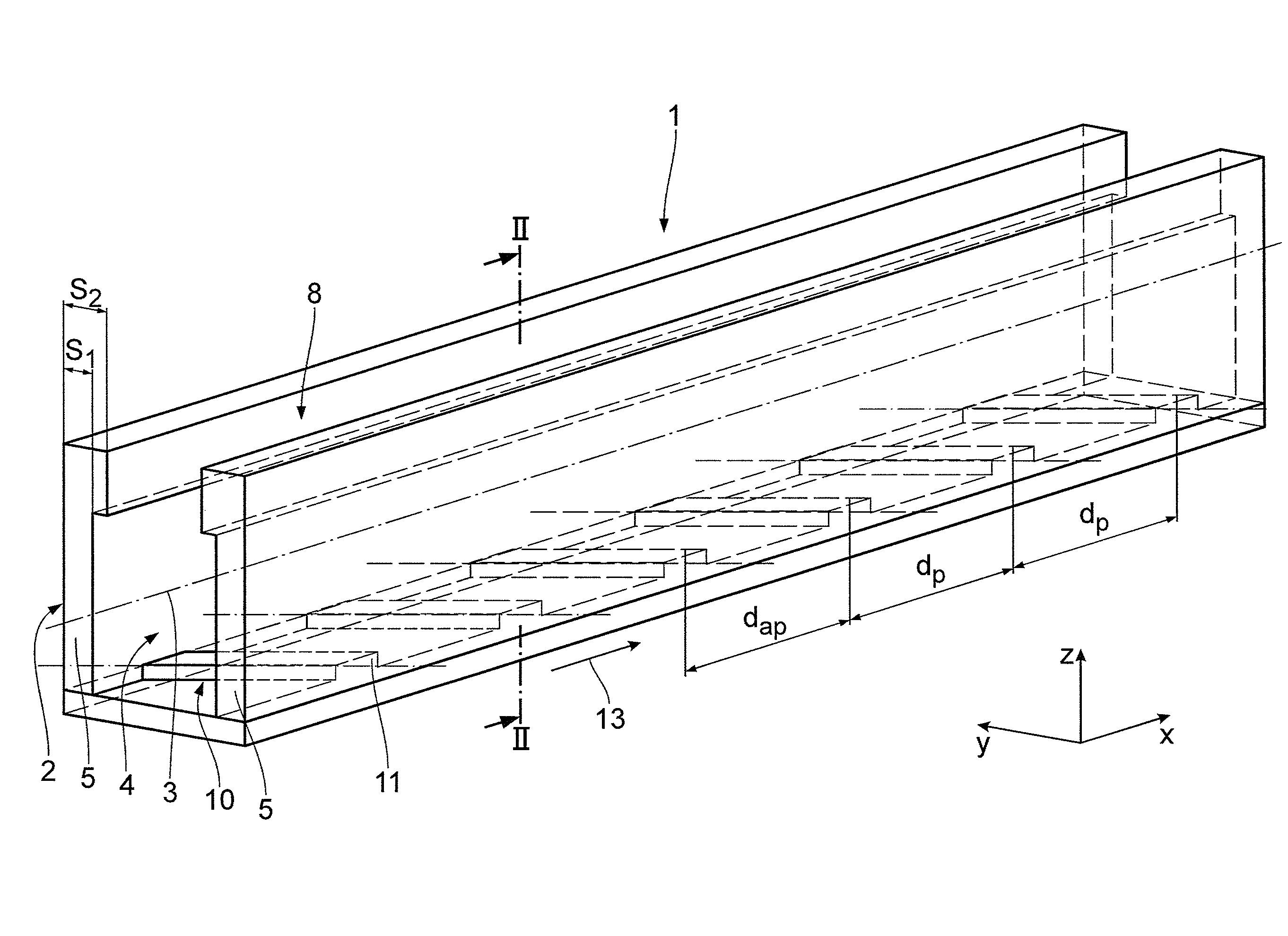
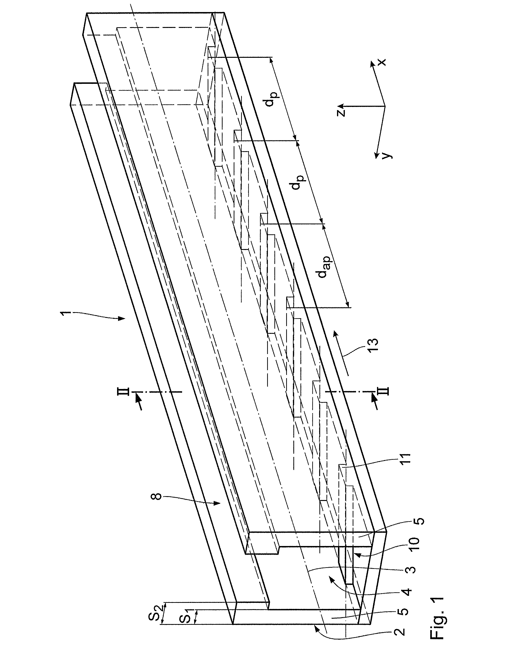
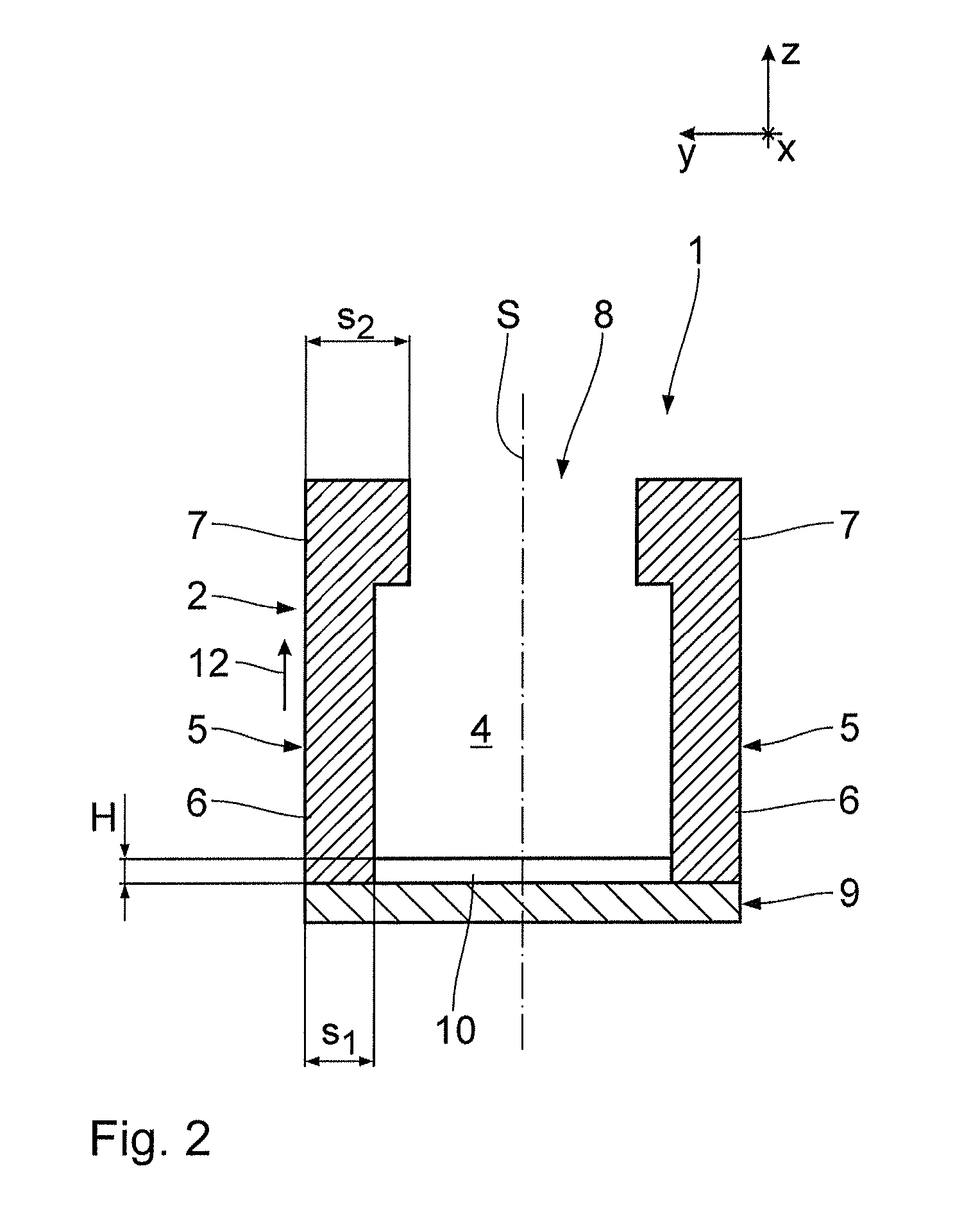
[0036]FIGS. 1 and 2 show a first exemplary embodiment of a waveguide antenna 1 for a radar antenna array which can be used particularly in motor vehicles for the purpose of determining and / or monitoring the distance. The waveguide antenna 1 is integrated into the radar antenna array in a manner known per se. The waveguide antenna 1 has a metal waveguide 2 which extends in an x direction and has a longitudinal axis 3 extending parallel to the x direction. For the propagation of a radar wave of a first mode in the x direction, the waveguide 2 delimits an inner space 4. The radar wave in the first mode propagates in the inner space 4 with a waveguide wavelength λ1.

[0037]The waveguide antenna 1 according to the exemplary embodiment shown is particularly adapted to guide the dominant mode TE10 in the waveguide 2. For this purpose, the waveguide 2 has a substantially U-shaped cross-section oriented in a z direction which is perpendicular to the x direction, said cross-section having two s...


PUM


Abstract

A waveguide antenna for a radar antenna array, particularly for use in motor vehicles, includes a metal waveguide extending in an x direction and having a longitudinal axis, which, for the propagation of a radar wave of a first mode in the x direction, delimits an inner space, wherein in order to specifically convert the first mode to a second mode of the radar wave which is different from the first mode and to couple the second mode out of the waveguide, a plurality of structural elements arranged in the x direction are provided which extend into the inner space and wherein adjacent structural elements have a distance which is larger than half a waveguide wavelength of the radar wave of the first mode or larger than half a free-space wavelength, depending on which of the two wavelengths is smaller.

Description

CROSS REFERENCE TO RELATED APPLICATIONS[0001]This application is the U.S. National Phase Application of PCT / DE2011 / 000305, filed Mar. 24, 2011, which claims priority to German Patent Application No. 10 2010 013 690.9, filed Mar. 31, 2010, the contents of such applications being incorporated by reference herein.FIELD OF THE INVENTION[0002]The invention relates to a waveguide antenna for a radar antenna array, particularly for use in motor vehicles.BACKGROUND OF THE INVENTION[0003]Such antennas are known, for example, from U.S. Pat. No. 5,572,228, which is incorporated by reference, wherein they are realized in a mechanically pivoting manner by letting a surface-structured drum rotate in close proximity to a dielectric waveguide. The surface structuring of the drum is realized by individual metal strips, the distance of which varies when the drum rotates within the region of the dielectric waveguide. This effects power to be coupled out of the dielectric waveguide via a so-called leak...

Claims


Application Information

Patent Timeline
Patent Type & Authority Patents(United States)
IPC IPC(8): G01S7/521H01Q13/00H01Q1/32G01S7/03H01Q13/28
CPCH01Q13/00G01S7/032H01Q1/32H01Q13/28
Inventor MOBIUS, ARNOLDFEY, WOLFGANG
Owner CONTI TEMIC MICROELECTRONIC GMBH
Why Eureka
Try Eureka