Inspection sensitivity evaluation method

a sensitivity evaluation and sensitivity technology, applied in the field of inspection sensitivity evaluation methods, can solve the problems of reducing the yield of lsi manufacturing, difficult to practically fabricate a real mask on which patterns are formed with the cds and positions shifted at such precision, and difficult to fabricate a real mask

Active Publication Date: 2015-11-24
NUFLARE TECH INC
View PDF8 Cites 4 Cited by
  • Summary
  • Abstract
  • Description
  • Claims
  • Application Information

AI Technical Summary

Problems solved by technology

One of major factors that decrease the yield of the LSI manufacturing is a pattern defect of a mask used when exposing and transferring a fine pattern onto a semiconductor wafer by the photolithography technology.
However, there is a problem that to practically fabricate a real mask on which patterns are formed with the CDs and positions shifted at such precision is difficult.
That is, there exists a problem of difficulty in practically fabricating a real mask where patterns are formed in a manner such that CDs and positions are shifted with the precision required for inspection sensitivity of the inspection apparatus in connection with recent miniaturization trend of patterns.
Accordingly, for realizing measurement of a CD deviation and a positional deviation by an inspection apparatus, there is a problem that to evaluate inspection sensitivity of the apparatus is difficult.

Method used


Image

  • Inspection sensitivity evaluation method
  • Inspection sensitivity evaluation method
  • Inspection sensitivity evaluation method

Examples


first embodiment

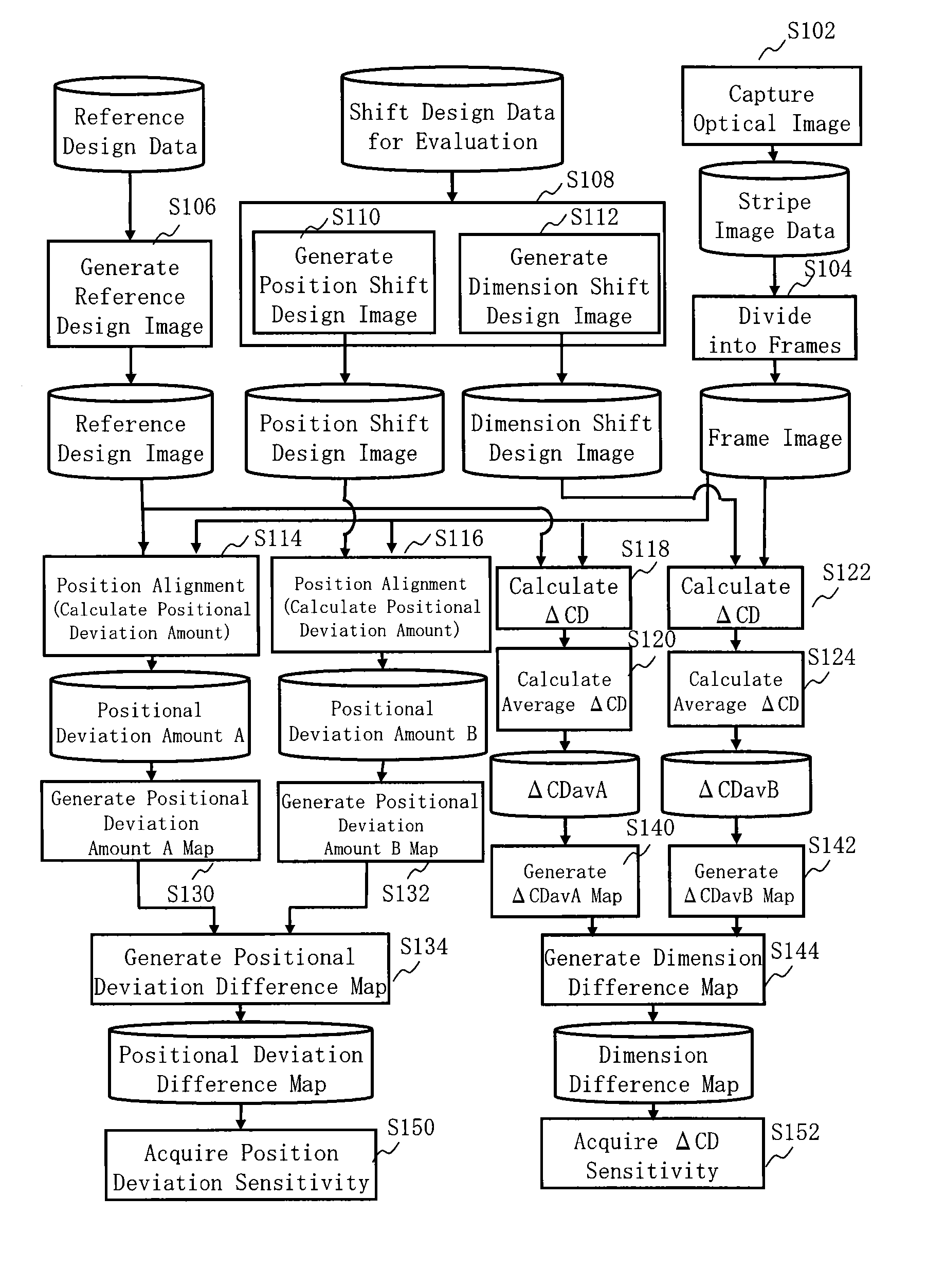
[0024]In Embodiments, there is described an inspection sensitivity evaluation method that can evaluate whether it is possible to detect a CD deviation or a positional deviation shifted at required precision.

[0025]With regard to precision required for inspection sensitivity of an inspection apparatus, it is difficult to fabricate a real mask where patterns for evaluation are formed in a manner such that CDs and positions are shifted at the precision (several nanometers), such as each 0.1 to 0.2 nm. According to the first embodiment, conversely to what is described above, there is prepared “shift design pattern data” in which line widths (CDs) and positions are shifted with respect to design pattern data. Then, a mask fabricated based on a reference design pattern in which CD dimensions and positions are not shifted is used as a real mask.

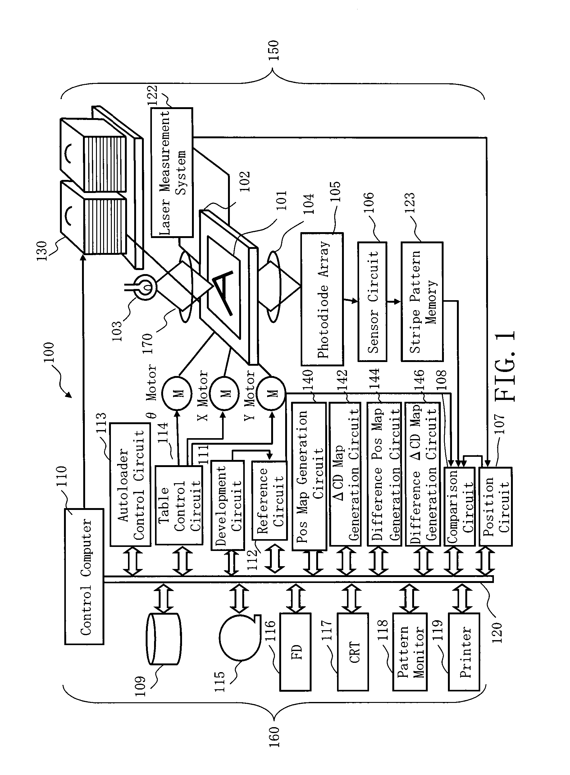
[0026]FIG. 1 shows the configuration of a pattern inspection apparatus according to the first embodiment. In FIG. 1, an inspection apparatus 100 tha...


PUM


Abstract

An inspection sensitivity evaluation method includes generating a reference design image where plural figure patterns are arranged, based on reference design data, generating plural position shift design images whose positional deviation amounts are mutually different such that positions of the plural figure patterns in the reference design image are uniformly shifted, acquiring an optical image of a photo mask fabricated based on the reference design data where there is no positional deviation from the plural figure patterns, calculating a first positional deviation amount between the reference design image and the optical image, calculating plural second positional deviation amounts each of which is a respective positional deviation amount between a corresponding position shift design image of the plural position shift design images and the optical image, and acquiring a detectable positional deviation amount by using the first and the plural second positional deviation amounts.

Description

CROSS-REFERENCE TO RELATED APPLICATION[0001]This application is based upon and claims the benefit of priority from the prior Japanese Patent Application No. 2013-107837 filed on May 22, 2013 in Japan, the entire contents of which are incorporated herein by reference.BACKGROUND OF THE INVENTION[0002]1. Field of the Invention[0003]The present invention relates to an inspection sensitivity evaluation method. More specifically, for example, it relates to an inspection sensitivity evaluation method of an inspection apparatus that inspects a pattern by irradiating laser lights or electron beams so as to acquire an optical image of the pattern to be inspected.[0004]2. Description of Related Art[0005]In recent years, with the advance of high integration and large capacity of a large scale integrated circuit (LSI), the line width (critical dimension) required for circuits of semiconductor elements is becoming progressively narrower. Such semiconductor elements are manufactured by exposing an...

Claims


Application Information

Patent Timeline
Patent Type & Authority Patents(United States)
IPC IPC(8): G06K9/00G06T7/00
CPCG06T7/001G06T2207/10061G06T2207/30148
Inventor HASHIMOTO, HIDEAKIKIKUIRI, NOBUTAKA
Owner NUFLARE TECH INC
Why Eureka
Try Eureka