Fuel cell

a fuel cell and cell technology, applied in the field of fuel cells, can solve the problems of metal ions dissolving and damage to the portion of the electrolyte membrane facing the outer end of the metal separator, and achieve the effects of preventing metal ions from the dissolution of metal separators, preventing degradation of solid polymer electrolyte membranes, and simple and economical structures

Active Publication Date: 2015-12-01
HONDA MOTOR CO LTD
View PDF4 Cites 0 Cited by
  • Summary
  • Abstract
  • Description
  • Claims
  • Application Information

AI Technical Summary

Benefits of technology

[0010]The present invention has been made to solve the problems of this type, and an object of the present invention is to provide a fuel cell having simple and economical structure in which it is possible to prevent dissolution of metal ions from metal separators, and suppress degradation of solid polymer electrolyte membranes as much as possible.
[0013]In the present invention, the frame shaped barrier layer is provided at least around the first electrode catalyst layer or around the second electrode catalyst layer. The frame shaped barrier layer has electrical insulating capability. Further, it is preferable that this frame shaped barrier layer has metal ion impermeability. Therefore, even if there is a potential increase or potential gradient from a position adjacent to the end of the first electrode catalyst layer to the outer portion where only the second electrode catalyst layer is present, dissolution of the metal ions from the outer ends of the metal separators can be suppressed. Further, even if water stagnation occurs, the solid polymer electrolyte membrane can be protected suitably. Thus, with the simple and economical structure, dissolution of metal ions from the metal separators can be prevented, and degradation of the solid polymer electrolyte membrane can be prevented as much as possible.

Problems solved by technology

Thus, portion of the electrolyte membrane 1 facing the outer ends of the metal separators tends to be damaged by the dissolved metal ions.

Method used


Image

  • Fuel cell
  • Fuel cell
  • Fuel cell

Examples


first embodiment

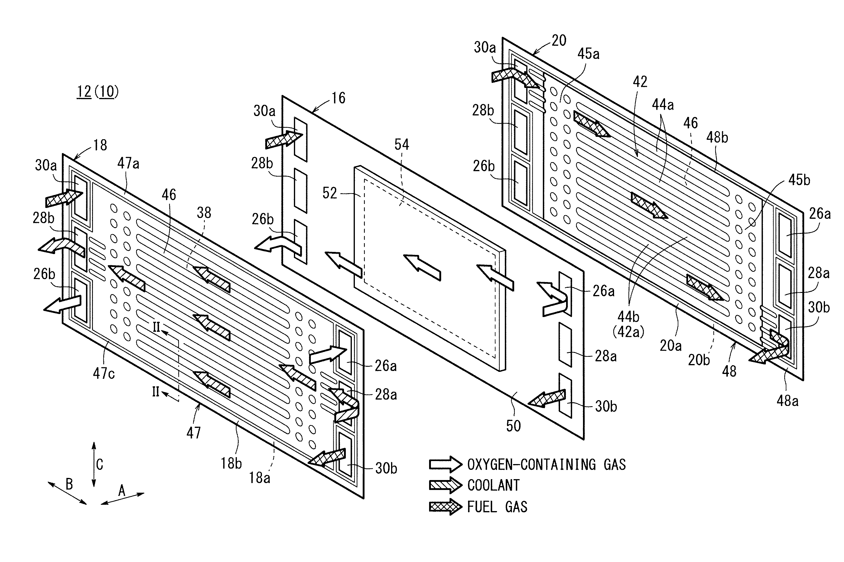
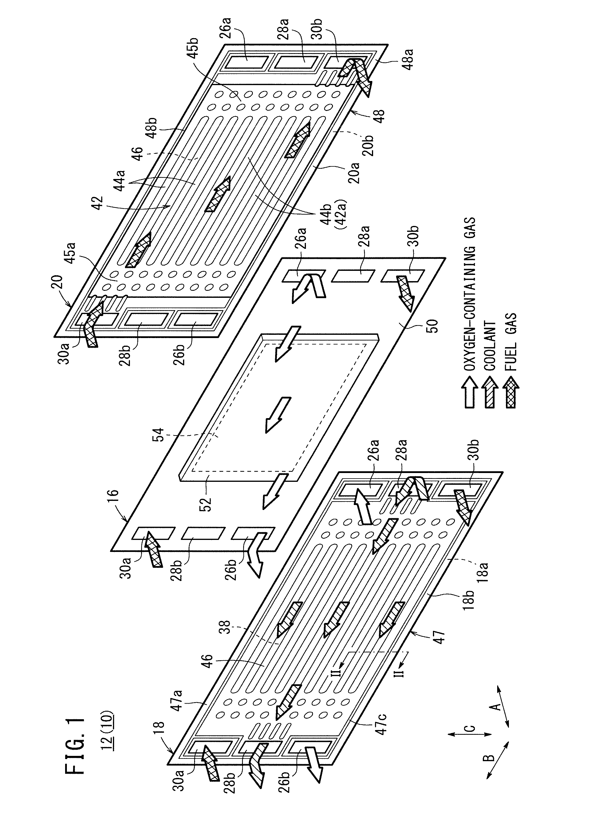
[0046]A plurality of power generation cells 12 shown in FIGS. 1 and 2 are stacked together upright in a horizontal direction indicated by an arrow A to form a fuel cell 10 according to the present invention.

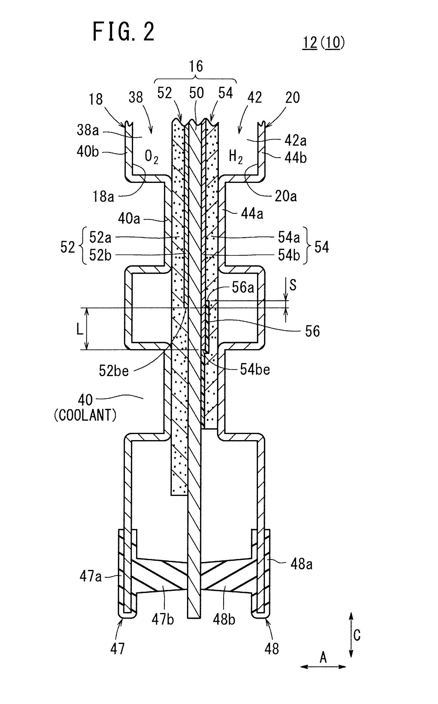
[0047]Each of the power generation cells 12 has a laterally elongated shape, and includes a membrane electrode assembly (MEA) 16, and a first metal separator 18 and a second metal separator 20 sandwiching the membrane electrode assembly 16. Each of the first metal separator 18 and the second metal separator 20 is formed by corrugating a metal thin plate by press forming to have a corrugated shape in cross section (see FIG. 2).

[0048]Each of the first metal separator 18 and the second metal separator 20 is made of an aluminum plate, a stainless steel plate, a titanium plate, or a niobium plate.

[0049]At one end of the power generation cell 12 in a longitudinal direction indicated by an arrow B in FIG. 1, an oxygen-containing gas supply passage 26a for supplying an oxygen-containing ...

third embodiment

[0082]FIG. 7 is a cross sectional view showing main components of a power generation cell 12b of a fuel cell 10b according to the present invention.

[0083]In the third embodiment, a second metal separator 20 has a fuel gas flow grooves 42a of a fuel gas flow field 42 facing an outer end 54be of an anode side electrode catalyst layer 54b. Thus, at the outer end 54be of the anode side electrode catalyst layer 54b, it is possible reliably suppress stagnation of the fuel gas and the water produced in the power generation reaction.

fourth embodiment

[0084]FIG. 8 is a cross sectional view showing main components of a power generation cell 62 of a fuel cell 60 according to the present invention.

[0085]The power generation cell 62 includes a membrane electrode assembly (MEA) 64, and a first metal separator 18 and a second metal separator 20 sandwiching the membrane electrode assembly 64. The membrane electrode assembly 64 includes a cathode 52, an anode 54, and a solid polymer electrolyte membrane 50 interposed between the cathode 52 and the anode 54.

[0086]A frame shaped barrier layer such as a gas impermeable film 56 is provided on the outer portion of an anode side electrode catalyst layer 54b, and a frame shaped barrier layer such as a frame shaped gas impermeable film 66 is provided around a cathode side electrode catalyst layer 52b. An inner end 66a of the gas impermeable film 66 contacts an outer end 52be of the cathode side electrode catalyst layer 52b, or the inner end 66a of the gas impermeable film 66 is positioned betwee...


PUM

PropertyMeasurementUnit
surface sizeaaaaaaaaaa
impermeableaaaaaaaaaa
areaaaaaaaaaaa

Abstract

A membrane electrode assembly of a fuel cell includes a solid polymer electrolyte membrane, a cathode, and an anode. The surface size of a cathode side electrode catalyst layer of the cathode is smaller than the surface size of an anode side electrode catalyst layer of the anode. An inner end of a gas impermeable film provided around the anode side electrode catalyst layer and an outer end of a cathode side electrode catalyst layer are overlapped with each other on both sides of the solid polymer electrolyte membrane.

Description

CROSS-REFERENCE TO RELATED APPLICATIONS[0001]This application is based upon and claims the benefit of priority from Japanese Patent Applications No. 2012-156084 filed on Jul. 12, 2012 and No. 2013-139088 filed on Jul. 2, 2013, the contents all of which are incorporated herein by reference.BACKGROUND OF THE INVENTION[0002]1. Field of the Invention[0003]The present invention relates to a fuel cell including a membrane electrode assembly and a pair of metal separators sandwiching the metal separators. The membrane electrode assembly includes a solid polymer electrolyte membrane, a first electrode provided on one surface of the solid polymer electrolyte membrane, and a second electrode provided on the other surface of the solid polymer electrolyte membrane. The first electrode has a first electrode catalyst layer and a first gas diffusion layer, and the second electrode has a second electrode catalyst layer and a second gas diffusion layer. The surface size of the first electrode cataly...

Claims


Application Information

Patent Timeline
Patent Type & Authority Patents(United States)
IPC IPC(8): H01M8/10H01M8/02
CPCH01M8/1006H01M8/0273H01M8/1002H01M2008/1095Y02E60/521H01M8/1007Y02E60/50
Inventor YAMAZAKI, KEIKOFURUYAMA, MASATAKAKATO, TAKASHIJINBA, RYOSUMI, HIDEAKISHIBUYA, MASATAKA
Owner HONDA MOTOR CO LTD
Why Eureka
Try Eureka