
Wireless power supply system and multi-layer shim assembly

a wireless power supply and multi-layer technology, applied in the direction of magnets, safety/protection circuits, magnetic bodies, etc., can solve the problems of time-consuming and laborious, difficult management of connections, and difficulty in constructing a primary coil array, etc., to achieve the effect of easing manufacturing

Active Publication Date: 2015-12-08
PHILIPS IP VENTURES BV
View PDF11 Cites 64 Cited by
  • Summary
  • Abstract
  • Description
  • Claims
  • Application Information

AI Technical Summary

Benefits of technology

[0009]In an alternative embodiment, the shield can replace a shim opposite the power transfer surface, one example is a bottom shim in a multi-layer shim assembly. That is, the shield may include guides for aligning coils and channels for routing wires. By utilizing the shield as part of the multi-layer shim assembly, the thickness of the wireless power supply can be reduced.
[0014]It is desirable to provide a construction aid for aligning coils in an array where the performance of the wireless power solution is dependent on the geometric pattern of center to center spacing of the array. The multi-layer shim array assembly eases manufacturing by assisting in aligning coils, assisting in routing wires, and connecting the coil array to wireless power circuitry.

Problems solved by technology

Various problems can arise in constructing a primary coil array.
First, because each primary coil has at least two leads for connection to the wireless power supply circuitry, managing the connections can be difficult because of the number of connections to be routed.
It can be time consuming to make the individual connections between each coil and the wireless power circuitry.
Second, securing each of the primary coils in position can be tedious and time-consuming.
Poor alignment during manufacture can result in efficiency losses throughout the entire lifetime of the wireless power supply.
Too many wires crossing over the coils can have a negative impact on the thickness of the stack and the electromagnetic field generated by the array.
Although printed circuit board arrays can overcome some of the challenges associated with constructing a primary array, they can be inefficient, especially at higher power output levels.
Heat can also be an issue that is difficult to address in a printed circuit board array.
It can be more difficult to align and connect wire primary coils in a wire primary array than in a printed circuit board primary array, however efficiency and heat issues are less of an issue in a wire primary array than in printed circuit board array solutions.
Some rudimentary solutions for primary wire coil arrays have been attempted, but they are not satisfactory for high volume production situations and are limited to small arrays.

Method used


Image

  • Wireless power supply system and multi-layer shim assembly
  • Wireless power supply system and multi-layer shim assembly
  • Wireless power supply system and multi-layer shim assembly

Examples


Embodiment Construction

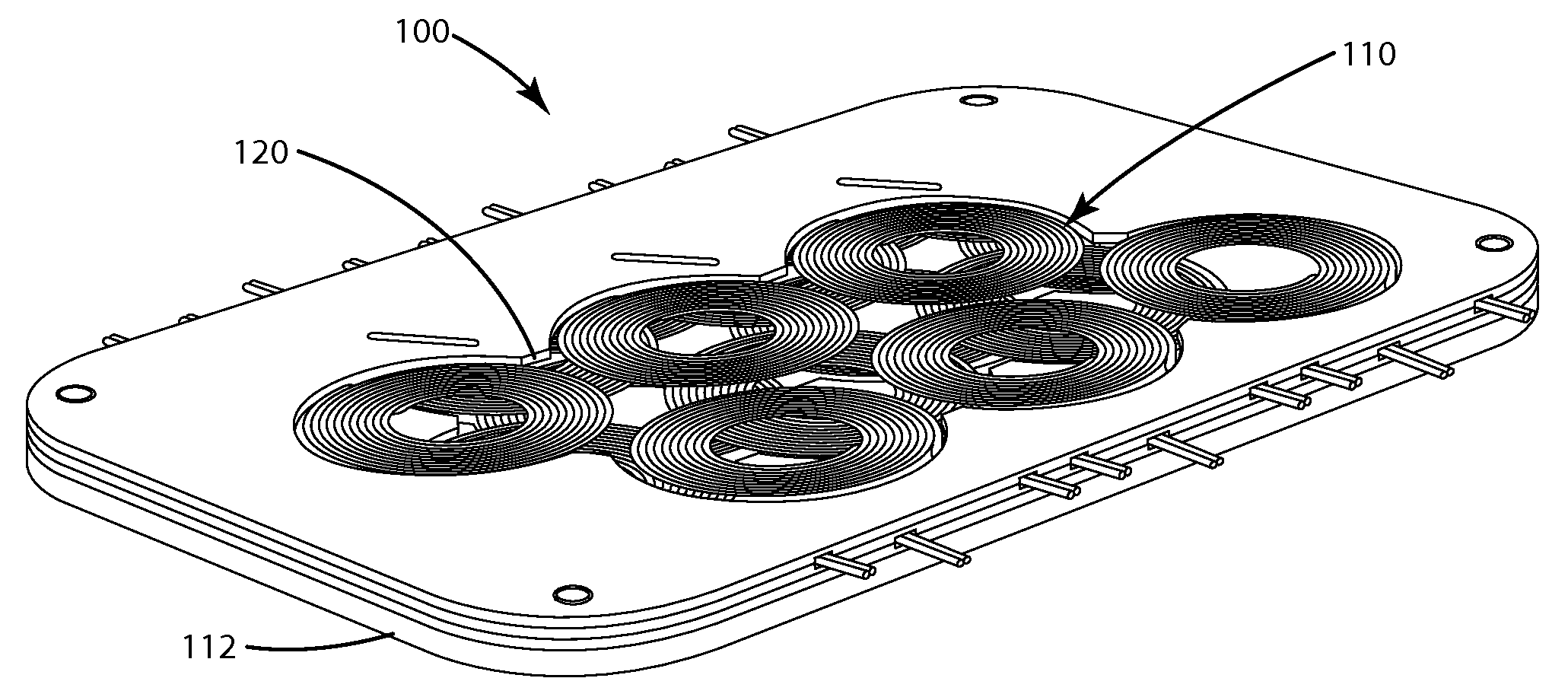
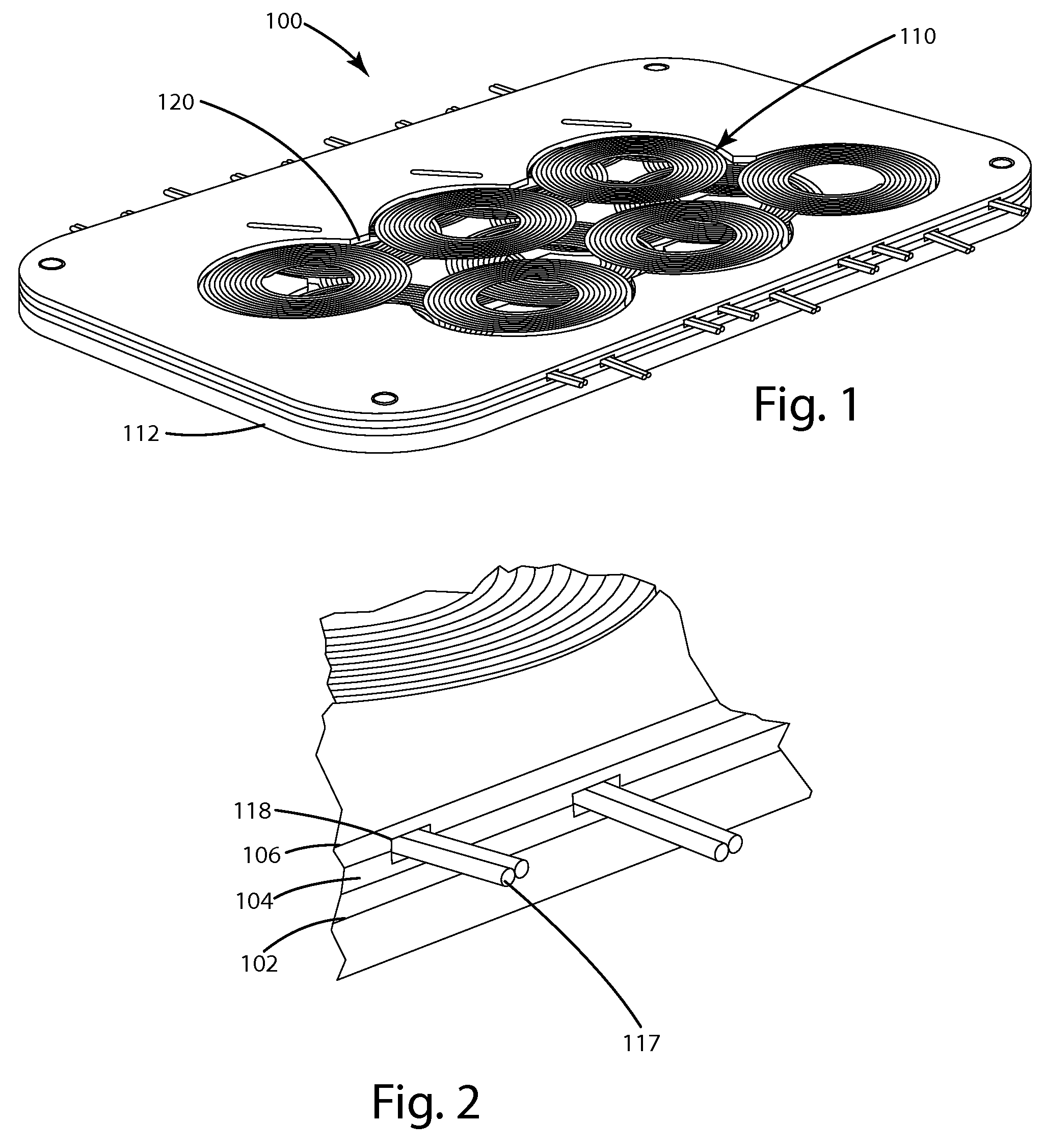
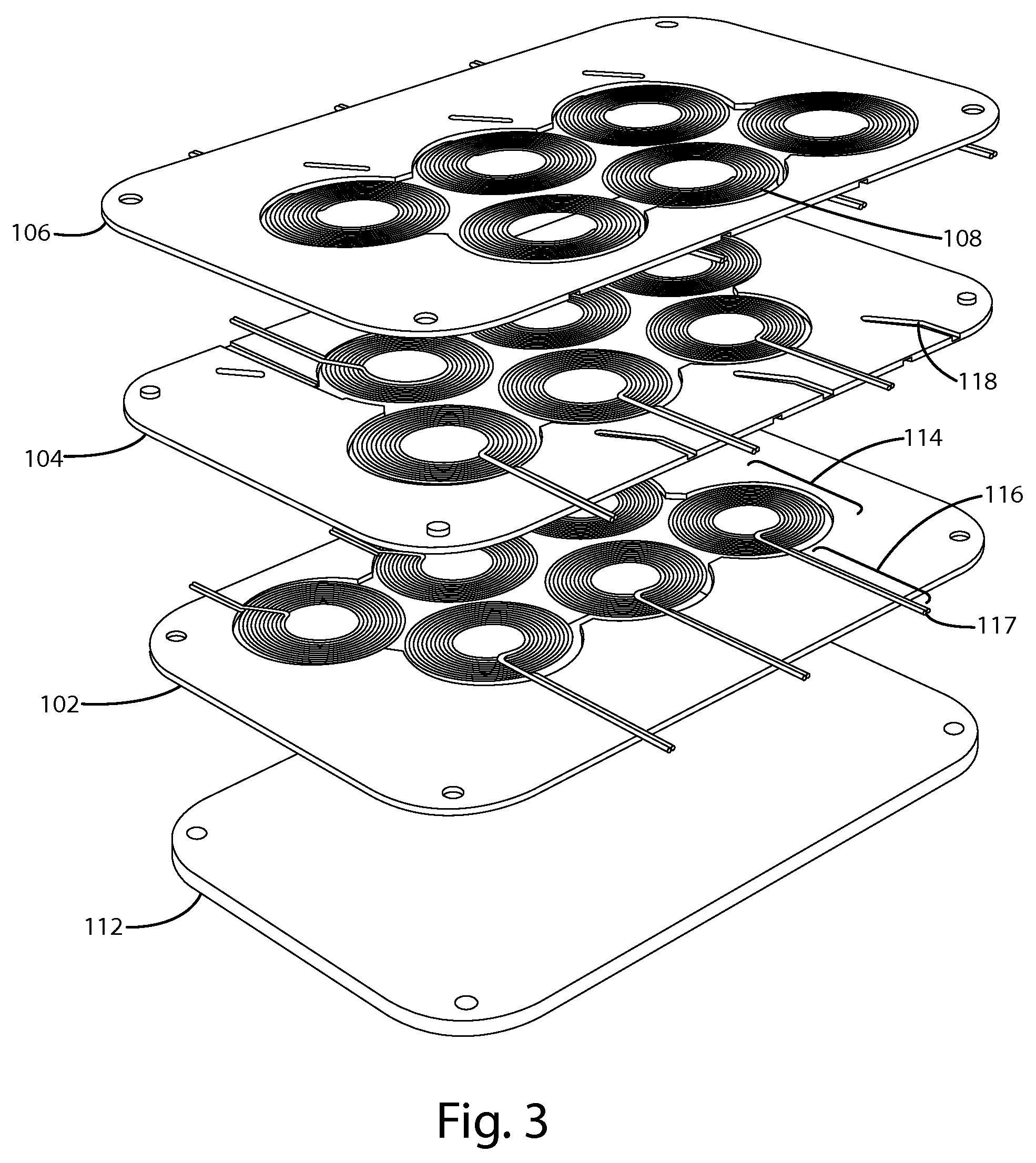
[0044]A multi-layer shim assembly constructed in accordance with one embodiment of the present invention is shown in FIGS. 1-3, and generally designated 100. In general, the multi-layer shim assembly includes multiple shims and multiple coils. Each shim aids in aligning some of the coils into a coil array, and collectively the shims together arrange the coils into a multi-layer coil array. The shims also aid in routing electricity between wireless power supply circuitry and the coils.

[0045]Referring to FIGS. 1-3, the depicted embodiment of the multi-layer shim assembly 100 includes three shims 102, 104, 106, eighteen coils 108 forming a multi-layer coil array 110, and a shield 112. Each shim aligns six coils into a single layer coil array and the three shims collectively align the eighteen coils into a three layer coil array.

[0046]Each coil 108 has a winding portion 114 and a transmission portion 116. The winding portion 114 includes one or more turns, such that when energized with ...


PUM

PropertyMeasurementUnit
non-conductiveaaaaaaaaaa
inductanceaaaaaaaaaa
routing poweraaaaaaaaaa

Abstract

A wireless power supply includes a multi-layer shim assembly. Each shim aids in alignment of coils and routing of conductors in a multi-layer coil array. A shield or PCB can be used as part of the multi-layer shim assembly. Wires can be routed through channels to the edge of the shim assembly or wires can protrude through a portion of the multi-layer shim assembly. Traces can be used to route current through the multi-layer shim assembly. Plastic shims can be created by over-molding coils with plastic.

Description

BACKGROUND OF THE INVENTION[0001]The present invention relates to wireless power supplies and methods for constructing wireless power supplies.[0002]Wireless power solutions are becoming more common. A simple wireless power solution can include a wireless power supply and a remote device, such as a mobile telephone. The wireless power supply can have a wall plug, wireless power circuitry, and a primary coil. Power is supplied from a wall outlet, the circuitry uses the power to energize the primary coil producing an electromagnetic field. The remote device includes a secondary coil, wireless power circuitry, and a load. When the remote device is placed in proximity of the electromagnetic field generated by the primary coil, the secondary coil receives the energy. The circuitry in the remote device uses the power from the secondary coil to energize the load, thereby transferring power from the wireless power supply to the remote device without the use of electrical contacts between th...

Claims


Application Information

Patent Timeline
Patent Type & Authority Patents(United States)
IPC IPC(8): H01F27/28H02J5/00H01F5/00H02J17/00H01F27/02H01F27/04H01F38/14H02J7/02H01F17/00
CPCH02J5/005H01F17/0013H01F27/022H01F27/04H01F38/14H02J7/025H02J17/00Y10T29/4902H02J50/12H02J7/00308H02J50/402H02J50/005H02J7/0044H02J50/10H02J50/90H02J50/40H02J50/70
Inventor BAARMAN, DAVID W.STONER, JR., WILLIAM T.MOES, BENJAMIN C.VAN DEN BRINK, JOSEPH C.SCHWANNECKE, JOSHUA K.KUYVENHOVEN, NEIL W.
Owner PHILIPS IP VENTURES BV
Learn More