Method for detecting the operational readiness of a jump lambda sensor

a technology of operational readiness and jump lambda, which is applied in the direction of electrical control, instruments, machines/engines, etc., can solve the problems of sensor signal not being usable, sensor signal distortion through the accompanying polarization of the sensor, and electrical wiring which does not permit measurement of internal resistance, so as to achieve short switched-off times and decrease the effect of internal resistan

Active Publication Date: 2015-12-29
ROBERT BOSCH GMBH
View PDF7 Cites 0 Cited by
  • Summary
  • Abstract
  • Description
  • Claims
  • Application Information

AI Technical Summary

Benefits of technology

[0020]To sum up, with the measurement of internal resistance the method according to the invention makes use of a criterion for operational readiness of the sensor which correlates directly with the temperature of the sensor element. This criterion is checked with reference to a rapid succession of measurements in order to detect the operational readiness of the sensor. No retarding additional criteria or complex plausibility checks are required, so that the method according to the invention can detect the operational readiness of the sensor very rapidly and reliably. A particular advantage of the method according to the invention is that the detection of operational readiness of the sensor is independent of the composition of the exhaust gas. With conventional methods for detecting operational readiness which, for example, evaluate the sensor voltage in relation to a reverse voltage, a delay in detecting operational readiness can occur if the exhaust gas lambda changes. This is precluded with the method according to the invention, since the criterion for the method according to the invention is only the temperature of the sensor ceramic or the internal resistance of the sensor correlating therewith, which is independent of exhaust gas composition. With the method according to the invention, therefore, no delays occur in detecting operational readiness if the exhaust gas composition fluctuates. Furthermore, with the method according to the invention, sensor faults cannot be misinterpreted as operational readiness of the sensor, as is possible with methods known from the prior art.
[0021]The method according to the invention makes use of the very reliable criterion of the internal resistance of the sensor as a measure for sensor temperature and therefore for operational readiness of the sensor, the polarization effects in the sensor caused by the internal resistance measurement being minimized according to the invention by adapting the frequency of the applied current pulses for measuring internal resistance to the state of the sensor. The method according to the invention therefore permits substantially faster and more reliable detection of operational readiness of the sensor in comparison to conventional methods, without the sensor signal being negatively influenced or falsified. This in turn allows the lambda control to be activated at an earliest possible time. This results in lower emissions, since the phase between engine start and activation of the lambda control can be kept as short as possible, emissions being disproportionately high especially in this phase.
[0022]The invention further comprises a computer program which executes all the steps of the method according to the invention if it is run on a computer or a control device. Finally, the invention comprises a computer program product with program code which is stored on a machine-readable carrier so that the method according to the invention is carried out when the program is run on a computer or a control device. The control device may be, for example, the central control unit of a motor vehicle or of an internal combustion engine. The embodiment of the invention as a computer program or a computer program product has the special advantage that no further components have to be installed in the motor vehicle in order to utilize the method according to the invention. The method according to the invention for detecting operational readiness of a jump lambda sensor can make use of the usual wiring of a jump lambda sensor, so that no further components have to be installed. All that is required is, for example, to implement the appropriate computer program, so that the method according to the invention can also be utilized especially advantageously with existing motor vehicles.
[0023]Further advantages and features of the invention are apparent from the following description of exemplary embodiments in conjunction with the drawing. However, the individual features may in each case be implemented in isolation or in combination with one another.

Problems solved by technology

Furthermore a jump lambda sensor is usually equipped with simpler electrical wiring which does not permit measurement of the internal resistance by high frequency alternating current upon starting the engine.
However, the pulse-shaped current for measuring the internal resistance leads to distortion of the sensor signal through the accompanying polarization of the sensor.
If the polarization has not decayed completely by the occurrence of next load pulse, further build-up of the sensor voltage can occur, so that the sensor signal is no longer usable.
Internal resistance measurement by pulse-shaped current cannot therefore be used for actually detecting operational readiness.
Depending on the exhaust gas lambda, therefore, the speed of detection of operational readiness of the sensor varies with this procedure, so that a delay in detecting operational readiness occurs, with a disadvantageous effect on the exhaust gas after-treatment through too-late activation of the lambda control.
It is further disadvantageous in this case that a fault in the sensor can be misinterpreted as operational readiness of the sensor, since a deviation of the sensor voltage from the reverse voltage can also be caused by a sensor fault.
However, taking account of these additional criteria further delays detection of the operational readiness of the sensor, with the accompanying disadvantages for the exhaust gas after-treatment and the emissions produced.

Method used


Image

  • Method for detecting the operational readiness of a jump lambda sensor
  • Method for detecting the operational readiness of a jump lambda sensor

Examples


Embodiment Construction

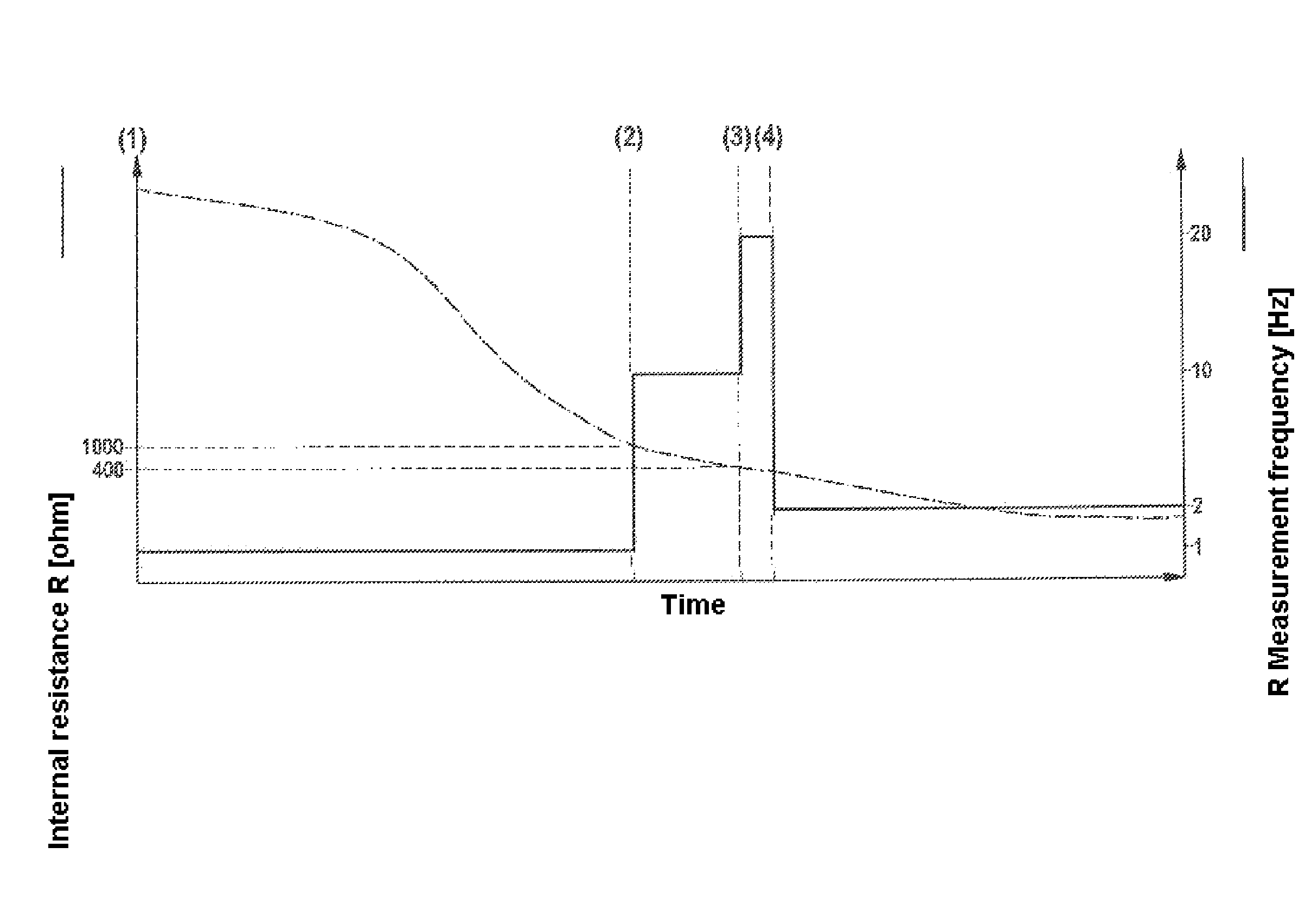
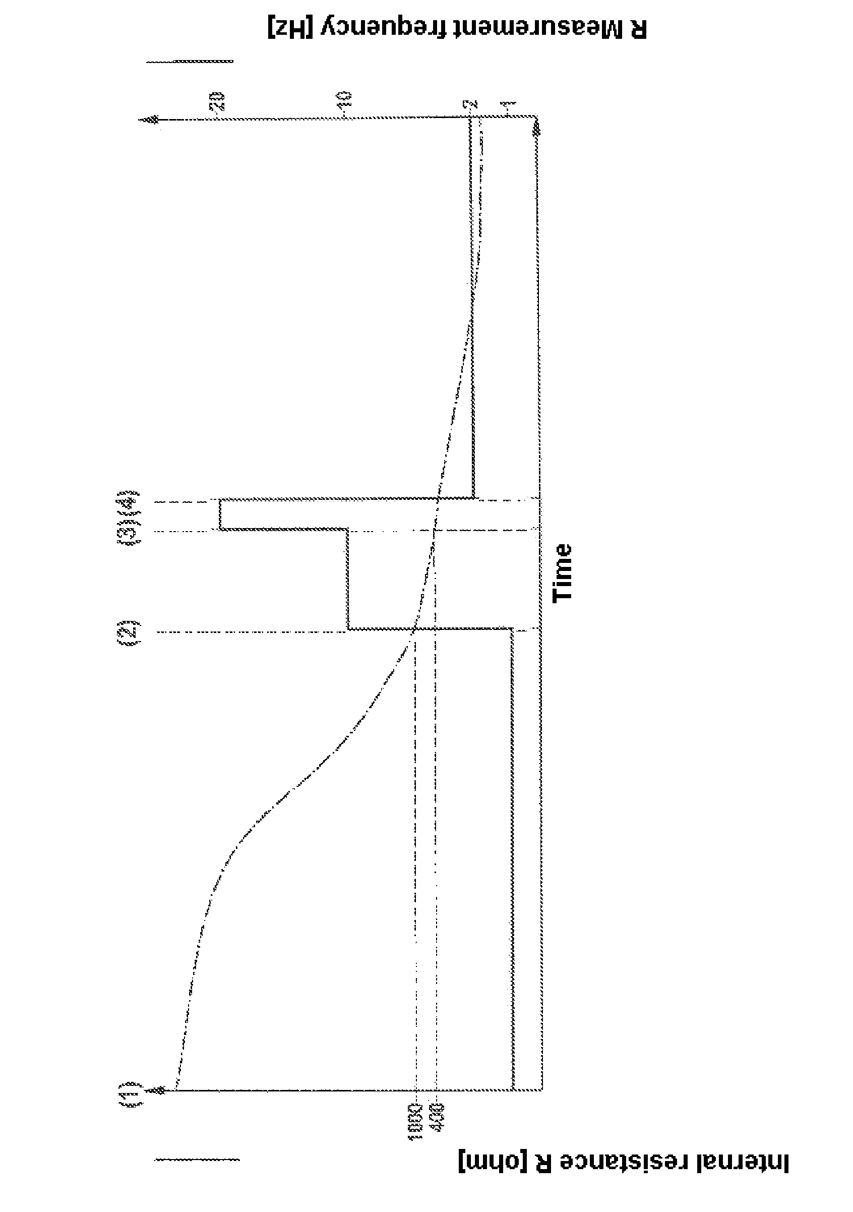
[0026]The method according to the invention utilizes the internal resistance of a jump lambda sensor as the criterion for detecting attainment of operational readiness of the sensor. A single-valued relationship exists between the sensor internal resistance and the sensor element temperature, the sensor element temperature exceeding a given temperature threshold when the sensor internal resistance simultaneously falls below a corresponding resistance threshold. Operational readiness of the sensor is reached when the internal resistance of the sensor has fallen below a given threshold. According to the invention, the internal resistance of the sensor is already measured before the sensor is operationally ready. Only by measuring prior to operational readiness of the sensor can attainment of operational readiness of the sensor be detected without delay. The sensor internal resistance is measured by applying a pulsed current to the sensor. According to the invention, in order to avoid ...


PUM


Abstract

In a method for detecting the operational readiness of a jump lambda sensor associated with an internal combustion engine the internal resistance of the sensor is determined as the criterion for the operational readiness of the sensor. The internal resistance is measured by applying a pulsed current to the sensor, the frequency of the current being selected as a function of the state of the sensor (1, 2, 3, 4).

Description

BACKGROUND OF THE INVENTION[0001]The present invention relates to a method for detecting the operational readiness of a jump lambda sensor, the internal resistance of the sensor being measured as the criterion for the operational readiness of the sensor.THE STATE OF THE ART[0002]In order to detect the concentration of oxygen in the exhaust gas of an internal combustion engine, lambda sensors are used in present-day engine control systems. The oxygen concentration in the exhaust gas of the internal combustion engine is determined by means of the lambda sensors, so that the supply of air and fuel to the internal combustion engine can be controlled via a lambda feedback control loop in such a way that an optimum composition of the exhaust gas can be attained for exhaust gas after-treatment by catalytic converters provided in the exhaust gas tract of the internal combustion engine.[0003]Various forms of lambda sensors are known. In the case of a two-point lambda sensor, also referred to...

Claims


Application Information

Patent Timeline
Patent Type & Authority Patents(United States)
IPC IPC(8): G01M15/10F02D41/14
CPCG01M15/104F02D41/1496F02D41/1455Y02T10/40
Inventor FEY, MICHAEL
Owner ROBERT BOSCH GMBH
Why Eureka
Try Eureka