
Method, device and system for compensating brightness of a liquid crystal module

a liquid crystal module and brightness compensation technology, applied in static indicating devices, cathode-ray tube indicators, instruments, etc., can solve the problems of uneven light and dark appearance in the final product, waste a lot of manpower, financial and material resources without achieving the desired actual, and achieve the effect of improving the product yield

Active Publication Date: 2015-12-29
HISENSE VISUAL TECH CO LTD
View PDF14 Cites 9 Cited by
  • Summary
  • Abstract
  • Description
  • Claims
  • Application Information

AI Technical Summary

Benefits of technology

[0006]Embodiments of the present invention relate to a method, device and system for compensating the brightness of liquid crystal module to eliminate the dark region of the liquid crystal module.
[0010]A method, device and system according to the embodiments of present invention eliminate product dark region of the liquid crystal module not reaching the factory standard and consequently improve product yield by means of making detection and brightness compensation for a large number of products with the aid of the image acquisition, image processing and circuit driving.

Problems solved by technology

For the LCM, issues such as technical reasons or as various zero units failing to meet the design requirements in the design and manufacturing process will lead to a phenomenon of uneven light and dark appearing in the final product.
The phenomenon includes, for example, light leak problem caused by an extrusion to the LCD flat panel due to structure parts production failing to meet the precision requirement for the design, shadow caused by the failure to meet a designed mixed light distance, bright-dark uniformity caused by a uneven optical diaphragm, and other undesirable phenomenon.
The above problems can be completely solved by a solution in which the design is modified and the machining accuracy of zero unit is improved, but this kind of scheme will waste a lot of manpower, financial and material resources without achieving a desired actual result.

Method used


Image

  • Method, device and system for compensating brightness of a liquid crystal module
  • Method, device and system for compensating brightness of a liquid crystal module
  • Method, device and system for compensating brightness of a liquid crystal module

Examples


embodiment 1

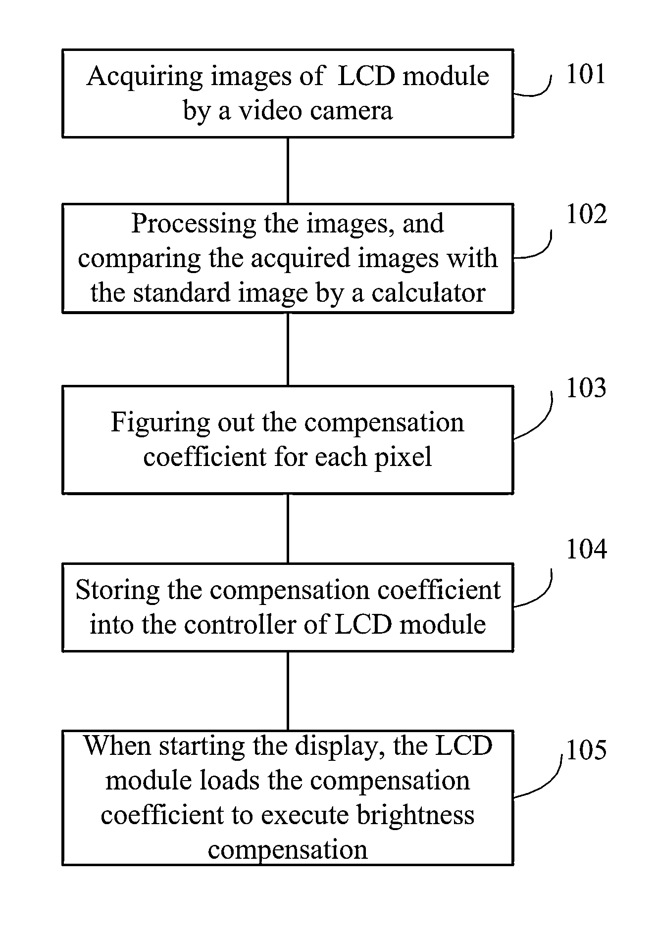
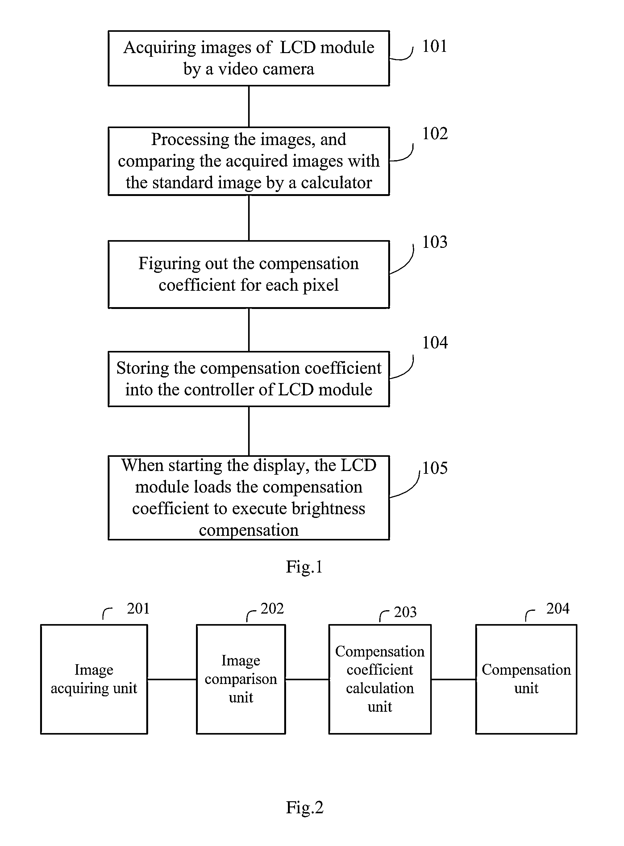
[0020]FIG. 1 is a flow chart of a method for compensating brightness of a LCM according to an embodiment of the present invention. In step 101, image acquiring is implemented to a liquid crystal module with scheduled image display to obtain the acquired image of the liquid crystal module. In step 102, the acquired image is compared with a standard image to find dark region. In step 103, the brightness difference between each pixel in the dark region and the corresponding pixel in the standard image is calculated to get compensation coefficients for each pixel in the dark region. In step 105, the compensation coefficients are stored into a display control circuit of the liquid crystal module. In step 105, When driving the liquid crystal module for display, the display control circuit compensates the backlight units corresponding to pixels in the dark region by using the compensation coefficients.

embodiment 2

[0021]FIG. 2 is a block diagram of a device for compensating brightness of a LCM according to an embodiment of present invention. Compensation apparatus shown in FIG. 2 includes an image acquiring unit 201 for acquiring image of liquid crystal module with scheduled image display to obtain the acquired image of the liquid crystal module. Also, the compensation apparatus also includes an image comparing unit 202 for comparing the acquired image with a standard image to find dark region. The compensation apparatus further includes a compensation coefficient calculating unit 203 for calculating the brightness difference between each pixel in the dark region and the corresponding pixel in the standard image to obtain compensation coefficients for each pixel in the dark region and storing the compensation coefficients into a display control circuit of the liquid crystal module. Additionally, the compensation apparatus includes compensating unit 204 which is used for compensating the backl...

embodiment 3

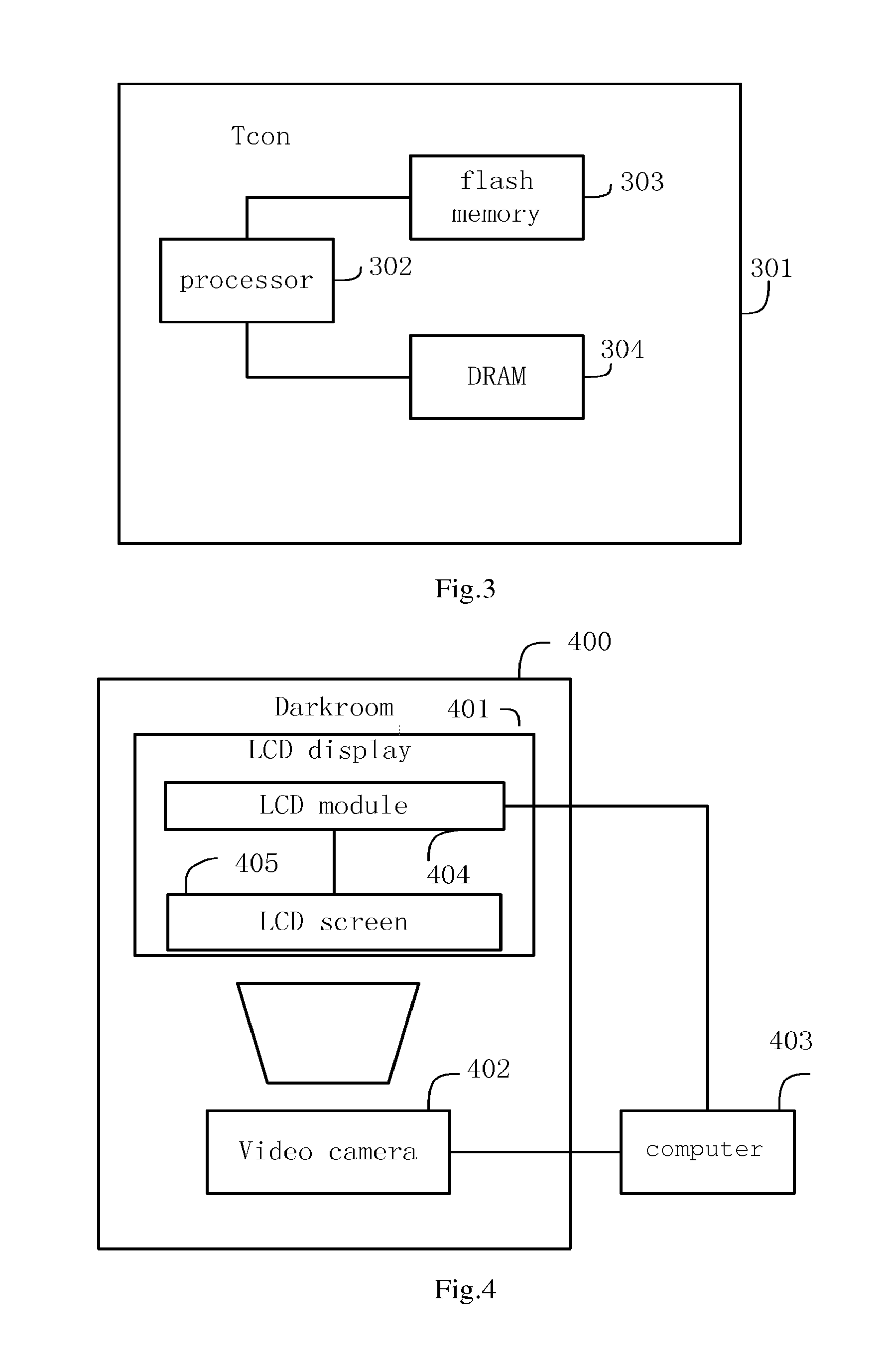
[0029]FIG. 4 is a block diagram of a system for compensating brightness of a LCM according to an embodiment of the present invention. Compensation system shown in FIG. 4 includes darkroom 400, LCM display 401, video camera 402 and computer 403. Video camera 402 may be a camera with charge-coupled components. LCM display 401 includes LCM 404 and LCD screen 405. In the system, the LCM display 401 and video camera 402 are located in the darkroom 400, video camera 402 can be fixed in the darkroom and totally opposite to the LCD screen 405, so that the video camera 402 can just gather a whole display image of LCD screen 405 of LCM display 401. LCM 404 and video camera 402 are connected to computer 403 respectively, so that the video camera 402 can transmit the acquired images to the computer 403 for processing, and the computer 403 can compensate LCM 404 according to the process result.

[0030]In an embodiment, one or more LCM displays 402 may be put in an assembly line. Images are acquire...


PUM


Abstract

A method for compensating the brightness of a liquid crystal module involves acquiring an image of a liquid crystal module to obtain the acquired image. The acquired image of the liquid crystal module is compared with a standard image to find a dark region. The compensation coefficient of each pixel in the dark region is calculated. In a display control circuit of the liquid crystal module, the calculated compensation coefficient of pixels is stored for compensating the backlight unit corresponding to pixels in dark region.

Description

TECHNICAL FIELD[0001]The invention relates to liquid crystal module (LCM) in general, and more specifically relates to a method, device and system for compensating brightness of liquid crystal module.BACKGROUND ART[0002]A LCM is mainly composed of a fluorescent tube, a light guide plate, a polarizing film, a filter plate, glass substrates, alignment films, liquid crystal materials, thin film transistors and so on. First of all, the LCM must project light using a backlight source, and the light will first pass through a polarizing film and then through liquid crystals. At this time, the liquid crystal molecules arrangement will change the polarization angle of the light spreading through the liquid crystal, and the light also must pass through a color filter and then another polarizing film. By changing the voltage value applied to the liquid crystal to control the light intensity and the color appearing finally, a combination of different tones can be shown on a liquid crystal panel...

Claims


Application Information

Patent Timeline
Patent Type & Authority Patents(United States)
IPC IPC(8): G09G5/02G09G3/34G09G3/36
CPCG09G5/02G09G3/36G09G3/34G09G3/006G09G3/3625G09G2320/0233G09G2320/0285G09G2320/0693G09G5/10
Inventor SONG, ZHICHENGQIAO, MINGSHENGLIU, WEIDONG
Owner HISENSE VISUAL TECH CO LTD
Learn More