Unlock instant, AI-driven research and patent intelligence for your innovation.

Three-dimensional object detection device

a detection device and three-dimensional technology, applied in the field of three-dimensional object detection devices, can solve the problem that high detection accuracy cannot be obtained in the detection of plant growths, and achieve the effect of high detection accuracy

Active Publication Date: 2016-01-19
NISSAN MOTOR CO LTD
View PDF16 Cites 2 Cited by
  • Summary
  • Abstract
  • Description
  • Claims
  • Application Information

AI Technical Summary

Benefits of technology

The patent text describes a method for detecting plant growth using image information. The method measures the speed at which the plant growth moves and compares it to other objects in the image. By assessing the level of variability in the movement speed, the method can identify if the detected object is a plant growth or another object that should not be detected. This allows for the proper detection of adjacent vehicles.

Problems solved by technology

However, the conventional technique detects shrubbery by image processing carried out by pattern matching.
Therefore, high detection accuracy cannot be obtained in detecting plant growths, and there may be cases in which a plant growth in a captured image is errantly detected as another vehicle traveling in an adjacent lane.

Method used


Image

  • Three-dimensional object detection device
  • Three-dimensional object detection device
  • Three-dimensional object detection device

Examples


first embodiment

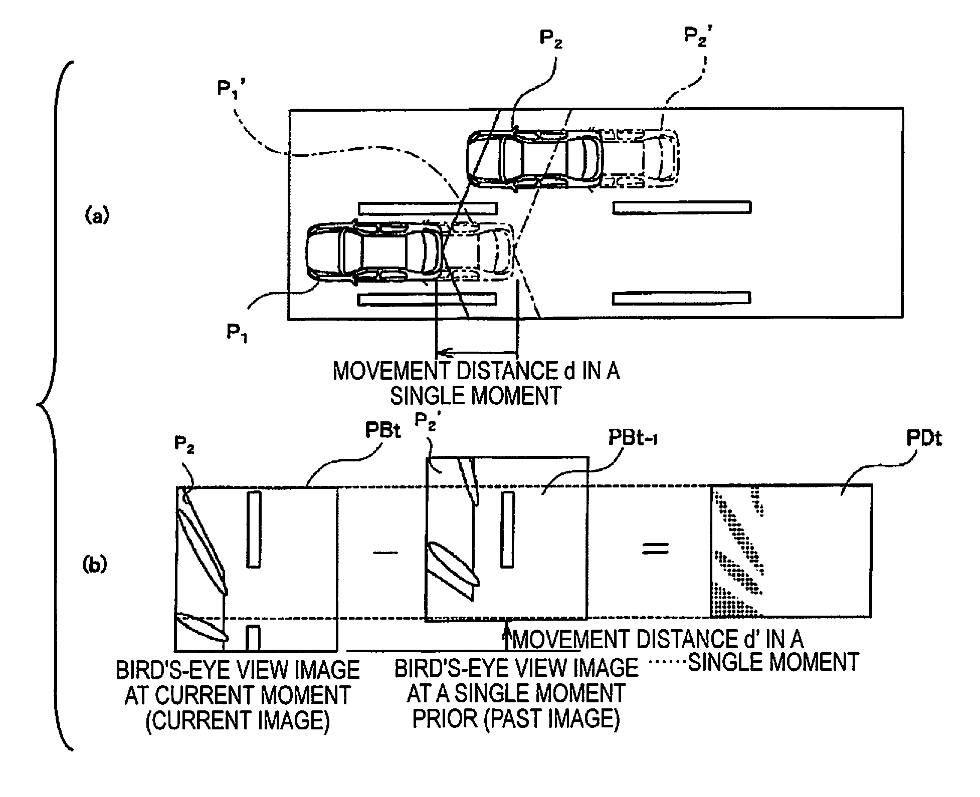
[0089]Thus, in the first embodiment, two images obtained at different moments are converted to bird's-eye view images, and a difference image PDt is generated based on the difference between the bird's-eye view images. The number of pixels that indicate a predetermined difference is counted along the direction in which the three-dimensional object collapses due to viewpoint conversion and a frequency distribution is formed to thereby generate a difference waveform DWt from the difference image PDt data. A three-dimensional object is furthermore detected based on the generated difference waveform DWt, and it is assessed whether the detected three-dimensional object is a plant, snow, guardrail, or other non-detection object based on the absolute value |ΔV| of the amount of change in time of the relative movement speed of the detected three-dimensional object. In this case, for example, discontinuous edge components tend to be detected in considerable numbers when a captured image in w...

second embodiment

[0106]The luminance difference calculation unit 34 determines the luminance difference between the attention point Pa and the reference point Pr. If the luminance difference between the attention point Pa and the reference point Pr is great, it is possible that an edge is present between the attention point Pa and the reference point Pr. In the second embodiment in particular, a perpendicular imaginary line is set as a line segment extending in the perpendicular direction in real space in relation to the bird's-eye view image, in order to detect a three-dimensional object present in the detection areas A1, A2. Therefore, there is a high possibility that there is an edge of a three-dimensional object in the location where the attention line La has been set when the luminance difference between the attention line La and the reference line Lr is high. Accordingly, the edge line detection unit 35 illustrated in FIG. 14 detects an edge line based on the luminance difference between the a...


PUM


Abstract

A three-dimensional object detection device includes an image capturing unit, an image conversion unit, a three-dimensional object detection unit, a movement speed calculation unit, a three-dimensional object assessment unit, a non-detection-object assessment unit and a control unit. The image conversion unit converts a viewpoint of the images to create bird's-eye view images. The three-dimensional object detection unit detects a presence of a three-dimensional object within the predetermined detection area based on difference waveform information. The movement speed calculation unit calculates a movement speed of the three-dimensional object. The non-detection-object assessment unit detect san amount of variability in the movement speed of the three-dimensional object, and assesses whether the three-dimensional object is a non-detection object based on the amount of variability. The control unit inhibits the three-dimensional object assessment unit from assessing that the three-dimensional object is the another vehicle based on the assessment results.

Description

CROSS-REFERENCE TO RELATED APPLICATIONS[0001]This application is a U.S. National stage application of International Application No. PCT / JP2013 / 054860, filed Feb. 26, 2013, which claims priority to Japanese Patent Application No. 2012-046670 filed in Japan on Mar. 2, 2012. The entire disclosure of Japanese Patent Application No. 2012-046670 is hereby incorporated herein by reference.BACKGROUND[0002]1. Field of the Invention[0003]The present invention relates to a three-dimensional object detection device.[0004]2. Background Information[0005]In a conventional technique, captured images captured by an image capturing device are subjected to image processing using pattern matching to thereby detect roadside plantings (see Japanese Laid-Open Patent Application No. 2008-227646).SUMMARY[0006]However, the conventional technique detects shrubbery by image processing carried out by pattern matching. Therefore, high detection accuracy cannot be obtained in detecting plant growths, and there ma...

Claims


Application Information

Patent Timeline
Patent Type & Authority Patents(United States)
IPC IPC(8): G06K9/00G08G1/16B60R1/00G06T7/20
CPCG06K9/00805B60R1/00G06T7/206G08G1/165G08G1/166G08G1/167B60R2300/607B60R2300/802G06T2207/10004G06T2207/20048G06T2207/20064G06T2207/30261G06T7/262G06V20/58B60R1/27G06F9/00G06T15/00B60Q9/005H04N23/63
Inventor FUKATA, OSAMUHAYAKAWA, YASUHISA
Owner NISSAN MOTOR CO LTD