Storage tank insulation joint apparatus and method

a technology for storage tanks and joints, applied in resiliently-mounted floors, flooring, building repairs, etc., can solve problems such as direct invasion of conventional expansion joints, thermal expansion and contraction, and existing expansion joints that are typically prone to water intrusion

Active Publication Date: 2016-01-26
NVENT SERVICES GMBH
View PDF39 Cites 4 Cited by
  • Summary
  • Abstract
  • Description
  • Claims
  • Application Information

AI Technical Summary

Problems solved by technology

Such expansion joints are especially useful when installed on roofs or upper surface(s) of storage tanks because such areas can be particularly susceptible to thermal expansion and contraction.
However, existing expansion joints are typically prone to water intrusion, as rain water and / or moisture from other sources have a tendency to collect on the upper surfaces of storage tanks.
Even without such low spots, driven rain and other precipitation can often directly invade conventional expansion joints.
Such water or moisture frequently results in oxidation or corrosion of the storage tank.
If enough water collects behind such insulation panels, the weight of such water can cause a catastrophic failure of the insulation system and its means of attachment to an underlying storage tank.
However, such efforts have proven to be ineffective at keeping water and moisture out of expansion joints, especially with respect to wind-driven precipitation or moisture.

Method used


Image

  • Storage tank insulation joint apparatus and method
  • Storage tank insulation joint apparatus and method
  • Storage tank insulation joint apparatus and method

Examples


Embodiment Construction

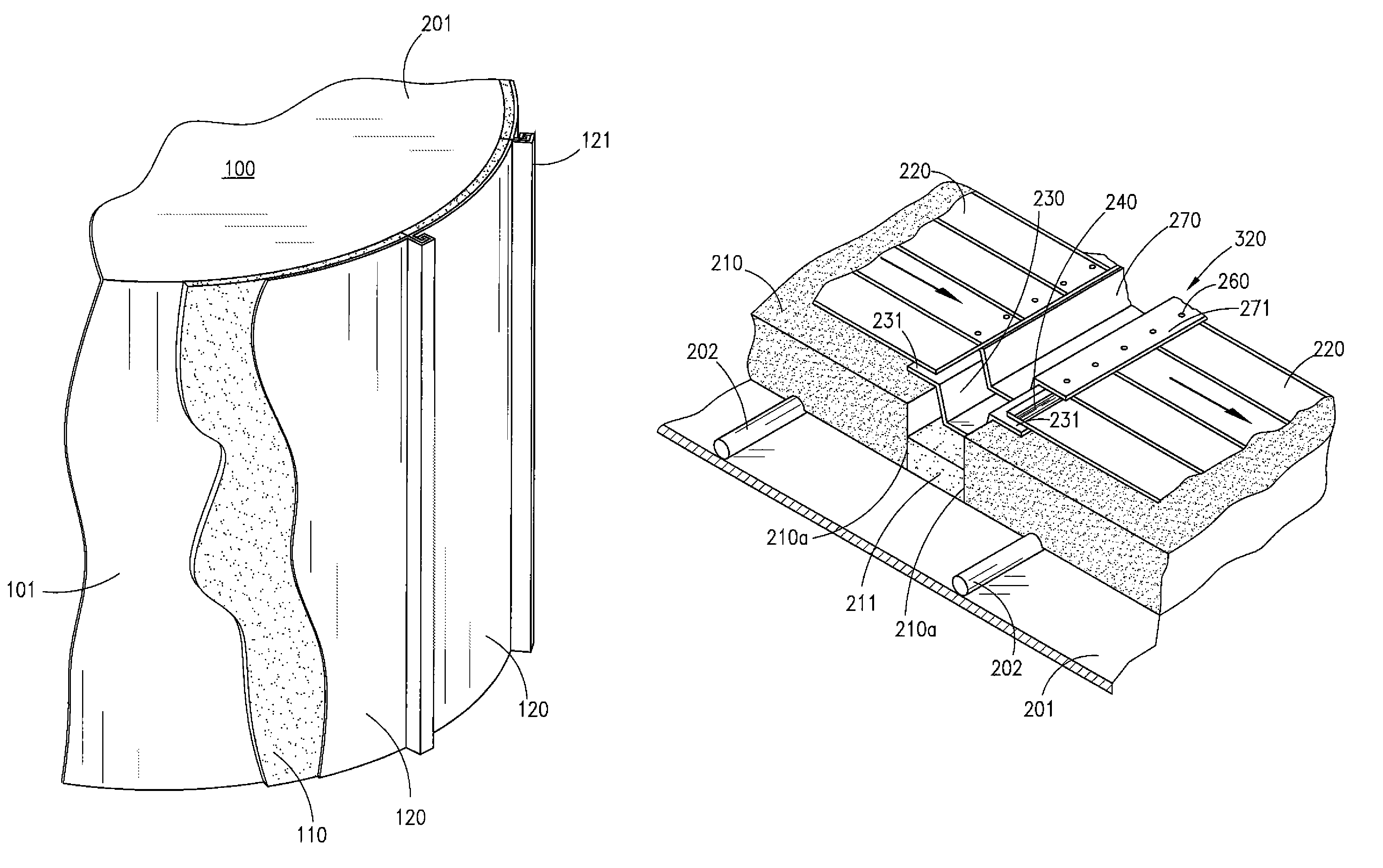
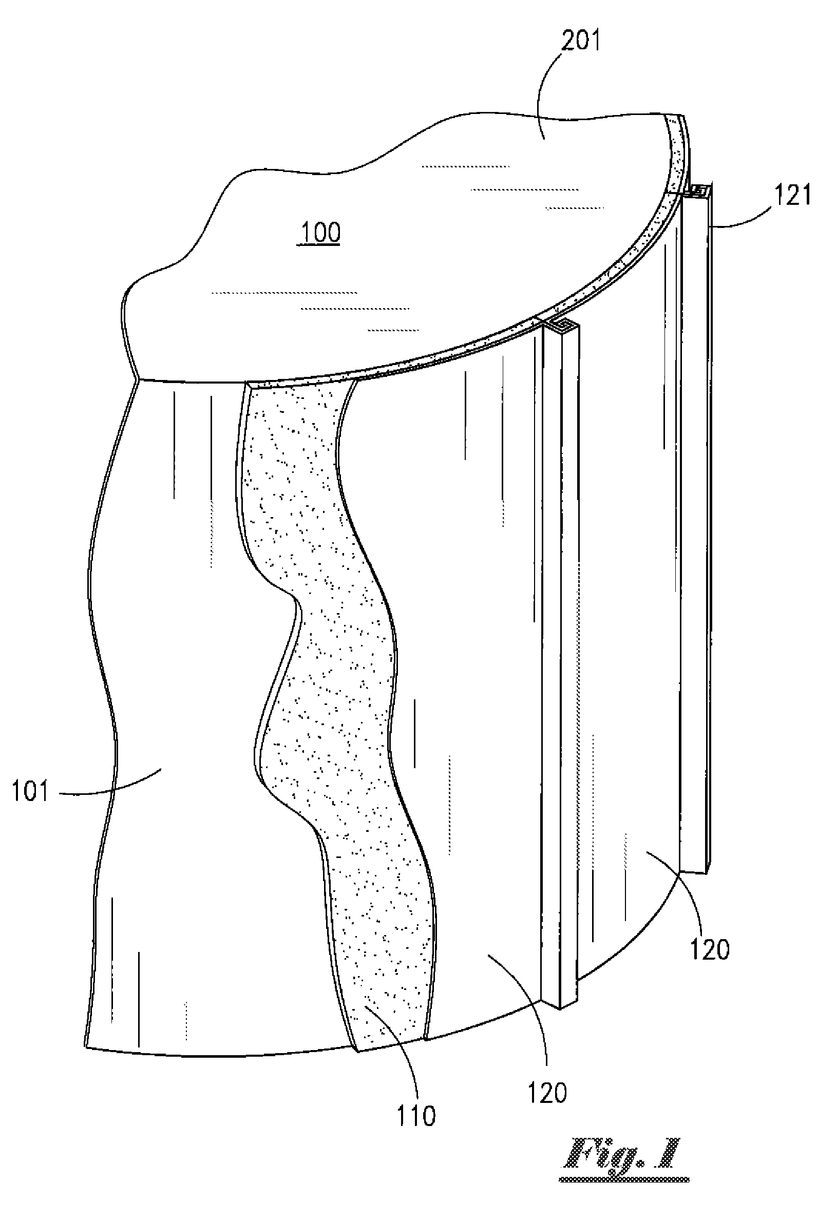
[0027]Referring to the drawings, FIG. 1 depicts a side perspective and partial sectional view of an externally insulated fluid storage tank 100. As depicted in FIG. 1, said storage tank 100 is substantially cylindrical, and has a substantially flat roof or upper surface. As depicted in FIG. 1, said storage tank 100 comprises substantially vertical side wall 101 and substantially horizontal roof section 201. By way of illustration, but not limitation, said tank side wall 101 can be constructed of steel or other suitable rigid material having desired strength and other characteristics.

[0028]As depicted in FIG. 1, storage tank 100 includes an external insulation system. Said external insulation system generally comprises interlocking prefabricated insulation panels 110 and jacketing material 120. A first layer of insulation panels 110 having desired thermal insulation and other characteristics is installed around the outer surfaces of storage tank 100. Thereafter, a second layer of jac...


PUM


Abstract

A joint for fluid storage tank insulation systems. A central expansion joint forms a fluid-sealed recessed channel having a ridge-like cap. Water and moisture are directed away from the central expansion joint by the ridge-like cap. Any water that breaches the cap enters the recessed channel and flows out of the expansion joint without damaging tank insulation material. With installations having multiple expansion joints, at least one of the expansion joints can be equipped with an inverted cap to form a gutter within such expansion joint.

Description

CROSS REFERENCES TO RELATED APPLICATION[0001]Priority of U.S. Provisional Patent Application Ser. No. 61 / 549,956, filed Oct. 21, 2011, incorporated herein by reference, is hereby claimed.STATEMENTS AS TO THE RIGHTS TO THE INVENTION MADE UNDER FEDERALLY SPONSORED RESEARCH AND DEVELOPMENT[0002]NoneBACKGROUND OF THE INVENTION[0003]1. Field of the Invention[0004]The present invention pertains to expansion joints for insulated fluid storage tanks. More particularly, the present invention pertains to expansion joints on thermally insulated fluid storage tanks. More particularly still, the present invention pertains to a expansion joints on fluid storage tanks, including upper surfaces of said fluid storage tanks, and a method for installing such expansion joints.[0005]2. Brief Description of the Prior Art[0006]The installation and use of thermal insulation on storage tanks is well known. Such thermal insulation can be particularly beneficial on large, flat-bottomed tanks used for storing ...

Claims


Application Information

Patent Timeline
Patent Type & Authority Patents(United States)
IPC IPC(8): E04F13/06E04H7/06E04F13/08E04F19/06
CPCE04H7/06E04H7/065E04F13/0864E04F19/066E04B1/6801E04B1/6803E04B1/6815E04D13/00E04H7/02
Inventor CHISM, CHRISTOPHER ALANRODRIGUEZ, JOE R.
Owner NVENT SERVICES GMBH
Why Eureka
Try Eureka