Breathable multi-component exhaust insulation system

a multi-component, exhaust insulation technology, applied in the direction of machines/engines, knitting, other domestic objects, etc., can solve the problems of difficult installation on the exhaust system, high manufacturing cost, and many drawbacks of prior art exhaust insulation sleeves, so as to improve the insulation performance, enhance the breathability of the insulating sleeves, and reduce the rate of fluid adsorption

Active Publication Date: 2013-11-21
NELSON GLOBAL PROD
View PDF10 Cites 35 Cited by
  • Summary
  • Abstract
  • Description
  • Claims
  • Application Information

AI Technical Summary

Benefits of technology

[0011]Optionally, a metal foil layer (or multiple metal foil layers) may be disposed between the braided insulation and the knit cover to improve insulation performance and reduce the rate of fluid adsorption into the insulation layers. The metal foil layer(s) may be made of aluminum, fiberglass reinforced aluminum, stainless steel, nickel, copper or tin, although any suitable metal foil may be used. Additionally, the metal foil layer(s) may be perforated or unperforated. The perforations enhance breathability of the insulating sleeve.

Problems solved by technology

Unfortunately, many of these prior art exhaust insulation sleeves suffer from various drawbacks.
Some are expensive to manufacture and difficult to install on exhaust systems.
Many do not provide sufficient breathability, so that when the insulation is exposed to water and rain, the water soaks into the insulation and does not dry quickly, which leads to rust and corrosion within the exhaust system.
Further, particularly in colder climates and coastal climates, salt from the roads can infiltrate the insulation system and accelerate corrosion of the system.
Moreover, many of the insulation sleeves and systems are made from materials that do not maintain their structural integrity over time due to wear and tear, and further degrade from the exposure to high temperatures associated with exhaust systems.

Method used


Image

  • Breathable multi-component exhaust insulation system
  • Breathable multi-component exhaust insulation system
  • Breathable multi-component exhaust insulation system

Examples


Embodiment Construction

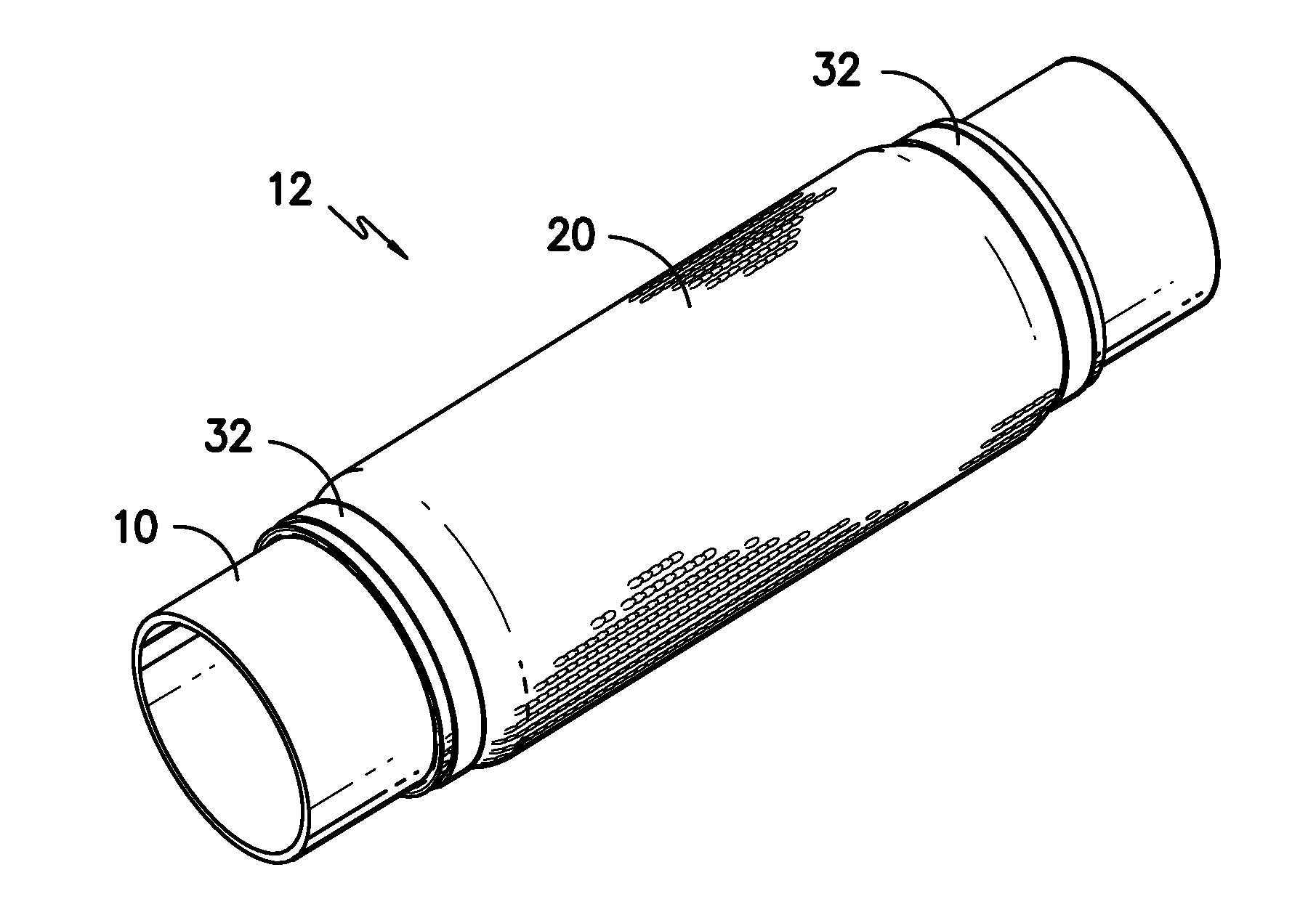
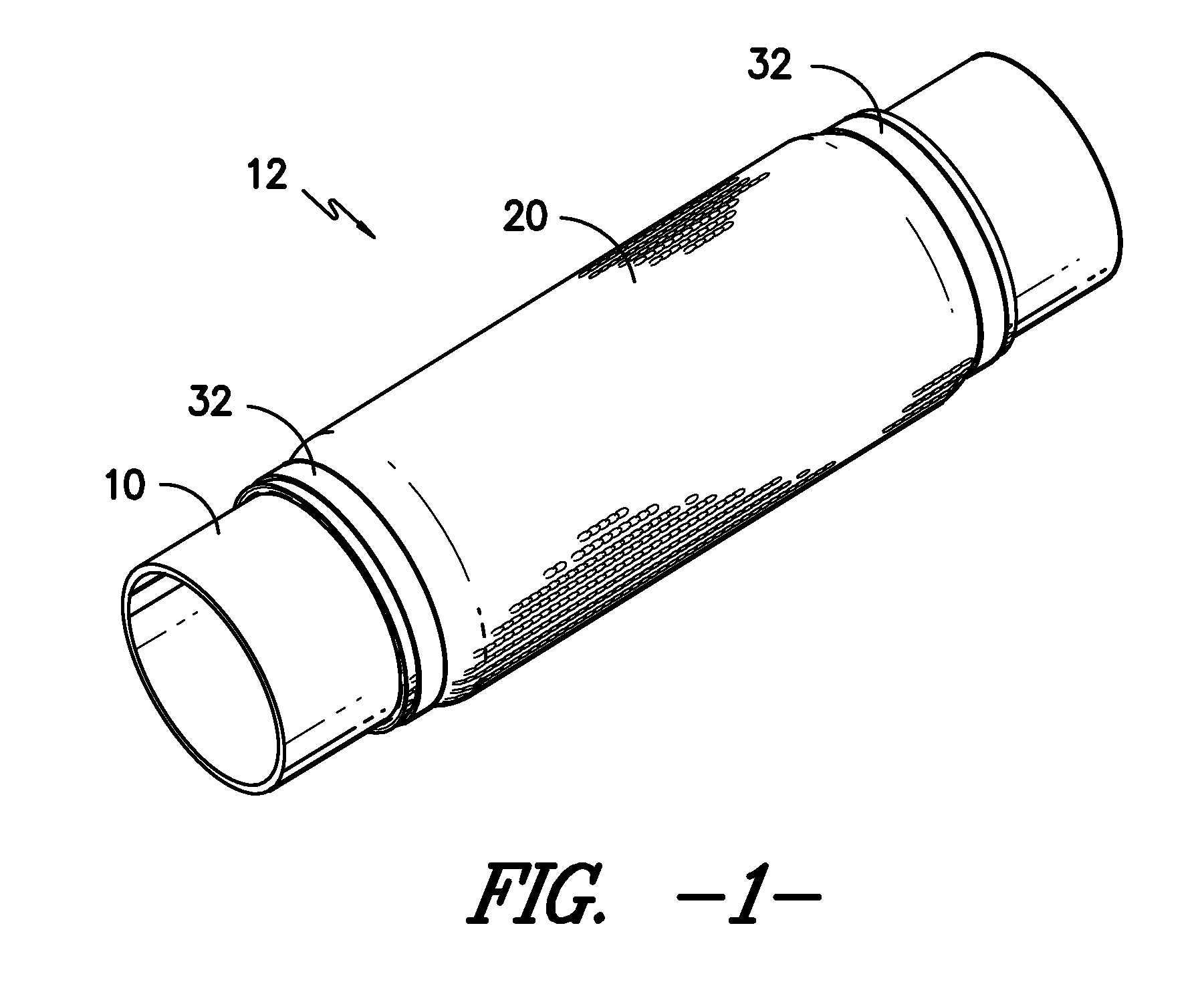
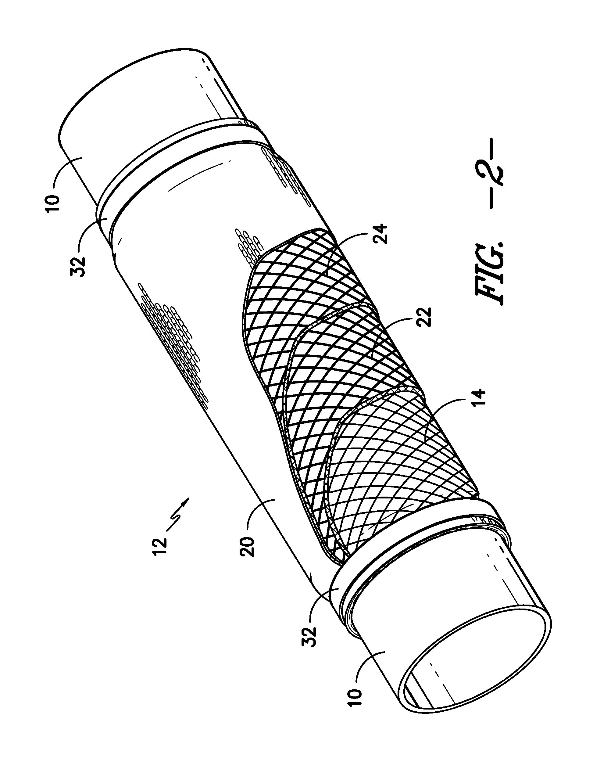
[0021]The present invention includes, in a first embodiment, a breathable, multi-layer exhaust insulation system, as shown in FIGS. 1-6. The exhaust insulation system includes a multi-layer sleeve 12, which can take one of several forms, and include a variety of components. The exhaust insulation system sleeve 12 is positioned about an outer side of a pipe 10, or the like.

[0022]Component Layers

[0023]The inner layer 14 or layers of the sleeve may include a braided or knit material made from high-temperature resistant materials including, but not limited to e-glass, s-glass, silica or ceramic. Braiding is the preferred textile construction of the inner layer, due to the fact that it is possible to deliver thicker profiles than knitted materials. In one preferred embodiment, the inner layer of silica is about 1 / 16″ thick and the glass layers are 0.2 inches thick. Further, another advantage of using braided material is that stretching the braided layer along the length of the exhaust pi...


PUM

PropertyMeasurementUnit
temperatureaaaaaaaaaa
thickaaaaaaaaaa
high-temperature resistantaaaaaaaaaa

Abstract

A breathable, multi-layer exhaust insulation system is provided. The system includes a multi-layer sleeve, wherein the first layer, which is positioned adjacent the exhaust system pipes, is a braided sleeve which may be constructed from high-temperature resistant materials such as e-glass, s-glass, silica or ceramic. Additional braided layers of material may be included, as well. An outside cover of material is preferably a circular knitted fabric that contains glass fibers and resin-based fibers. The knitted fabric forms a tube on the outside of the insulating layers, and may be formed from a core spun yarn, which includes a glass filament core and a high-melt fiber on the wrap. Optionally, the system may also include a perforated or unperforated metal foil layer and/or a tape wrap, and the various components may be configured as desired.

Description

BACKGROUND OF THE INVENTION[0001]The present invention relates generally to insulation for exhaust systems and other types of pipe systems that transport hot gases and other hot fluid materials. More specifically, the present invention relates to a multi-component sleeve that may be used, among other things, to fit exhaust systems on vehicles generally and large trucks in particular.[0002]Heretofore, various insulation systems have been used to insulate automotive and industrial exhaust systems. Exhaust insulation systems are used to maintain high temperature of exhaust gases in order to provide more efficient and complete combustion of fuels, and to protect surrounding components from the high exhaust temperatures. Additionally, maintaining high exhaust temperatures tends to increase the velocity of the exhaust gases through the system, which allows the engine cylinder to more fully evacuate and aids in the emission control processes. On large bore diesel trucks, insulating the exh...

Claims


Application Information

Patent Timeline
Patent Type & Authority Applications(United States)
IPC IPC(8): F16L9/14
CPCF16L59/029F01N13/1816F01N13/148F16L59/08D04B1/14D10B2505/12B32B5/08B32B5/22B32B5/26B32B1/08B32B2250/02B32B2250/03B32B2250/04B32B2250/20B32B2262/0261B32B2262/0269B32B2262/0276B32B2262/101B32B2262/105B32B2262/14B32B2307/304B32B2307/306B32B2597/00
Inventor GOULET, ROBERT JACQUE
Owner NELSON GLOBAL PROD
Why Eureka
Try Eureka