Wide angle and high resolution tiled head-mounted display device

a display device and wide angle technology, applied in static indicating devices, instruments, optics, etc., can solve the problems of large exit pupil diameter and high resolution, difficult to meet the requirements of large field of view and high resolution simultaneously in a conventional head-mounted display device employing a single display channel, image distortion on the pupil plane of the display located at the edges, etc., to avoid pupil aberration, no resolution variance, and keep the pupil diameter and eye clearance constant

Active Publication Date: 2016-01-26
THE ARIZONA BOARD OF REGENTS ON BEHALF OF THE UNIV OF ARIZONA +1
View PDF97 Cites 30 Cited by
  • Summary
  • Abstract
  • Description
  • Claims
  • Application Information

AI Technical Summary

Benefits of technology

[0043]The optical tiled head-mounted display device according to the present invention is compact and lightweight, and the exit pupil planes of all display channels are coincident, thus avoiding pupil aberration and keeping pupil diameter and eye clearance constant. Furthermore, there is no resolution variance in the overall field of view, thus preventing additional distortion. The tiled head-mounted display device according to the present invention can be readily applicable to augmented reality. In comparison, for a conventional head-mounted display device to be used in augmented reality, it is necessary to introduce a half mirror into the device to fold optical path in order to achieve optical transmission, thus requiring a complex and bulky structure.
[0044]Furthermore, the surfaces of the prisms according to the present invention for optical tiling can be formed continuous together as larger optical surfaces, each larger surface can be fabricated in one time and thus it does not require additional processing for the tiling surface. In addition, all optical surfaces of the prism of the display channels in the head-mounted display device can be formed integrally, thus reducing difficulty and complexity of the tiling process.

Problems solved by technology

However, there is a trade-off between compactness of optical system and imaging quality of head-mounted display.
However, it is difficult to achieve wide field of view, large exit pupil diameter and high resolution at the same time, due to the tradeoff relationships among these parameters.
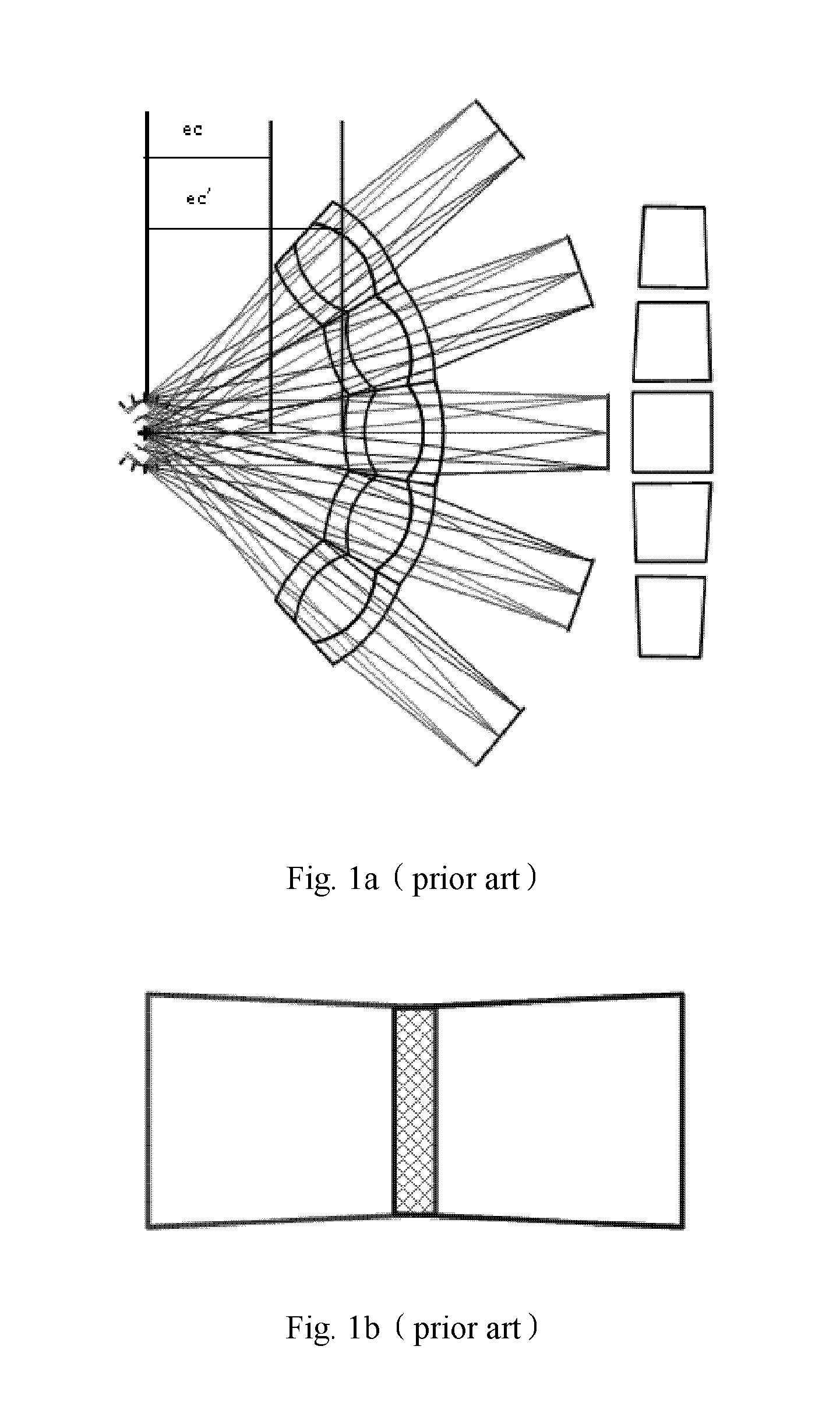
Therefore it is difficult to satisfy the requirements of large field of view and high resolution simultaneously in a conventional head-mounted display device employing a single display channel.
In this case, image magnification varies throughout the tiled system, resulting in image distortion on the pupil plane for the displays located at the edges.
Therefore, the images to be displayed on each display of the tiled optical system needs to be pre-warped, otherwise the user will observe distorted images.
Therefore, users may see discontinuous images when their eyeballs are moving.
The decrease of the effective exit pupil diameter may also lead to pupil aberration.
For a system tiled by a plurality of oculars, the structure of optical system is greatly complicated, and the weight and size of optical systems are increased significantly.
Moreover, the tiling process of the oculars with rotational symmetry is complex, requiring additional processes for the tiling surfaces.
Therefore, it is very difficult to process and assemble this tiled system with relatively high precision.

Method used


Image

  • Wide angle and high resolution tiled head-mounted display device
  • Wide angle and high resolution tiled head-mounted display device
  • Wide angle and high resolution tiled head-mounted display device

Examples


first embodiment

[0081]FIG. 5a is a schematic view of a tiled head-mounted display system according to a first embodiment of the present invention; FIG. 5b is a schematic view illustrating field of view of the tiled head-mounted display system according to a first embodiment of the present invention. As shown in FIG. 5a, a head-mounted display device according to the first embodiment of the present invention can comprise a first display channel 501 and a second display channel 502 tiled by the first mechanical tiling method as described above. The first display channel 501 is rotated by a first angle in YOZ plane about X-axis of a global coordinate system. The second display channel 502 is rotated by ±180° about Z axis which is in a direction along viewing axis of a human eye, and then rotated by the first angle in the opposite direction about X-axis of the global coordinate system. As shown in FIG. 5b, the tiled head-mounted display according to the first embodiment of the present invention has a h...

second embodiment

[0082]FIG. 6a is a schematic view of a tiled head-mounted display system according to a second embodiment of the present invention; FIG. 6b is a schematic view illustrating field of view of the tiled head-mounted display system according to a second embodiment of the present invention. As shown in FIG. 6a, a head-mounted display device according to the second embodiment of the present invention can comprise a first display channel 601 and a second display channel 602 tiled by the second mechanical tiling method as described above. The first display channel 601 is rotated by a second angle in XOZ plane about Y-axis of a global coordinate system. The second display channel 602 is rotated by the second angle in the opposite direction about Y-axis of the global coordinate system. As shown in FIG. 6b, the tiled head-mounted display according to the second embodiment of the present invention has a horizontal field of view of at least 70° and a vertical field of view of at least 30°.

third embodiment

[0083]FIG. 7a is a schematic view of a tiled head-mounted display system according to a third embodiment of the present invention; FIG. 7b is a schematic view illustrating field of view of the tiled head-mounted display system according to a third embodiment of the present invention. As shown in FIG. 7a, a head-mounted display device according to the third embodiment of the present invention can comprise a first display channel 701, a second display channel 702 and a third display channel 703 rotated by a predetermined angle about Y-axis of a global coordinate system. The second display channel 702 is tiled with the first display channel 701 and the third display channel 703 using the second mechanical tiling method, respectively. As shown in FIG. 7b, the tiled head-mounted display according to the third embodiment of the present invention has a horizontal field of view of at least 100° and a vertical field of view of at least 30°.


PUM


Abstract

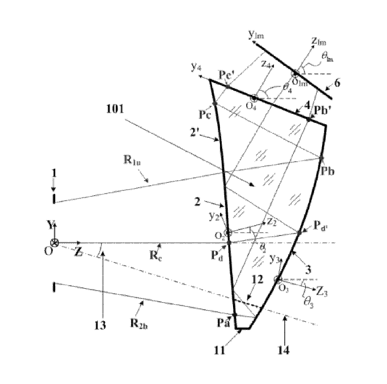
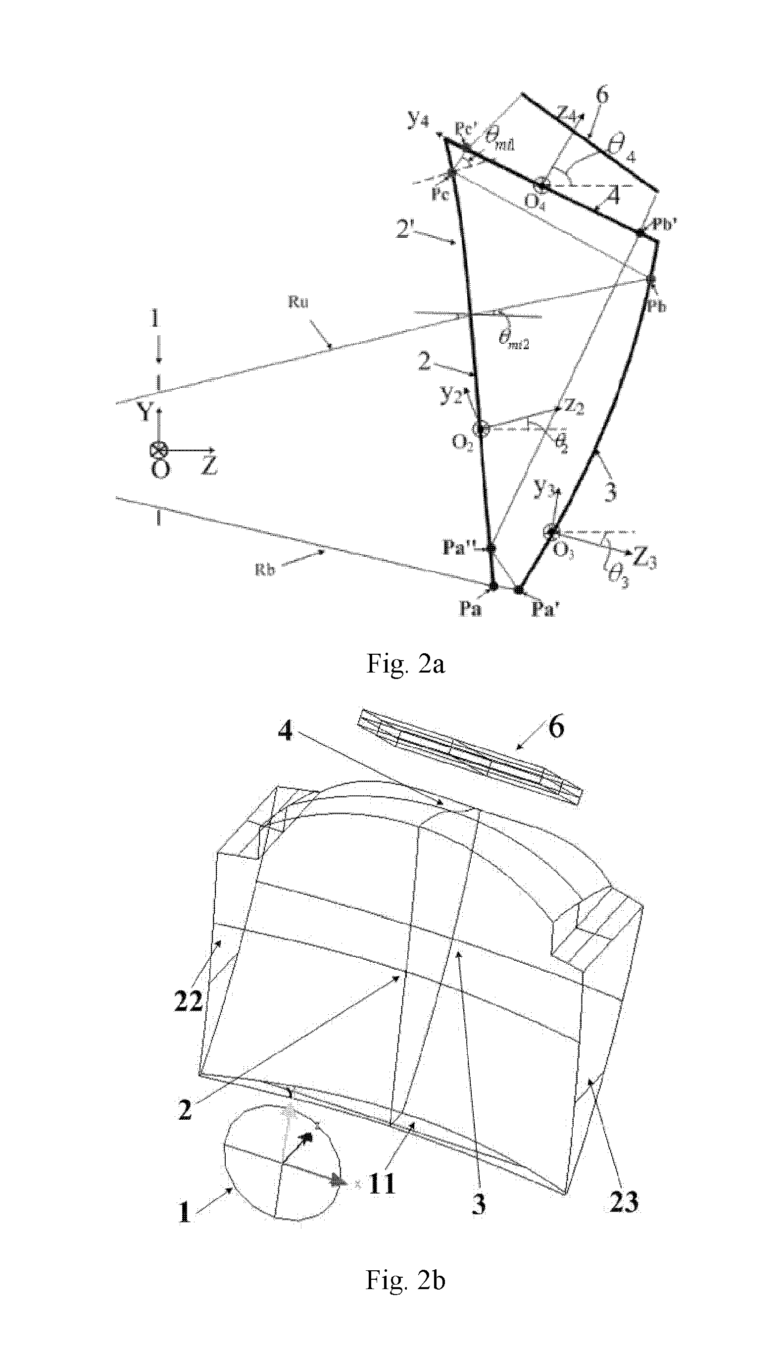
A tiled head-mounted display device comprises an optical component including a plurality of prisms with free-form surfaces, and a display component including a plurality of micro-displays (6), wherein the number of the micro-displays (6) and the number of the prisms with free-form surfaces is identical, and each prism with free-form surfaces and the corresponding micro-display (6) constitute a display channel. Each prism is a wedge prism including a first surface (2), a second surface (3) and a third surface (4). The exit pupil planes of each display channel are coincident, thus avoiding pupil aberration and keeping exit pupil diameter and eye clearance same as a single ocular. There is no resolution variance throughout the entire field of view, thus preventing extra trapezoid distortion. The tiled head-mounted display device is compact and lightweight, and provides wide field of view and high resolution. The tiled head-mounted display device can be readily applicable to augmented environments applications by simply adding an auxiliary free-form lens behind the prism with free-form surfaces.

Description

STATEMENT OF GOVERNMENT INTEREST[0001]This invention was partially funded by United States (“U.S.”) National Science Foundation Grant No. 0644446. The United States government has certain rights in the invention.RELATED APPLICATIONS[0002]This application is a 371 application of International Application No. PCT / CN2010 / 072376 filed Apr. 30, 2010.BACKGROUND OF THE INVENTION[0003]This invention was partially funded by National Natural Science Foundation of China grant nos. 61205024 and 61178038, and Hi-Tech Research and Development Program of China grant no. 2009AA01Z308.[0004]The present invention relates to a head-mounted display device, and in particular, to a tiled head-mounted display device comprising wedge-shaped prisms with free-form surfaces.[0005]Head-mounted display devices for virtual environment and augmented environment are popular products in display industry and have been extensively developed in recent years. Head-mounted display device can be used in consumer applicat...

Claims


Application Information

Patent Timeline
Patent Type & Authority Patents(United States)
IPC IPC(8): G09G5/00G02B27/01
CPCG02B27/0172G02B2027/011G02B2027/0123G02B5/04G02B2027/0147
Inventor CHENG, DEWENWANG, YONGTIANHUA, HONG
Owner THE ARIZONA BOARD OF REGENTS ON BEHALF OF THE UNIV OF ARIZONA
Why Eureka
Try Eureka