Antenna and front end module

a technology for front end modules and antennas, applied in antennas, antenna details, basic electric elements, etc., can solve the problems of difficult analysis of causes of performance degradation, increased radiation loss, and difficult to analyze the effect of performance degradation, so as to facilitate the manufacturing of antennas, reduce connection distances, and improve radiation characteristics

Active Publication Date: 2016-01-26
SAMSUNG ELECTRO MECHANICS CO LTD
View PDF16 Cites 11 Cited by
  • Summary
  • Abstract
  • Description
  • Claims
  • Application Information

AI Technical Summary

Benefits of technology

[0014]An aspect of the present invention provides an antenna and a front end module having an air cavity formed therein and a reduced connection distance with a signal processing module to improve radiation characteristics and facilitate the manufacturing thereof.

Problems solved by technology

However, in the case of the 801.11ad network standard, as a distance between an antenna and signal processing module is increased, radiation loss is increased.
For example, when an error of ±10% occurs in an actual manufacturing process at the time of using an LTCC manufacturing process, a resonance point may be shifted by about ±1 to 2 GHz, based on a signal within a millimeter wave band, a feeding structure may be complicated, and a degradation in performance may occur due to a mismatch between an antenna patch and a feeding line, such that it may be difficult to analyze causes of degradation in performance.
In addition, when the antenna and the signal processing module are connected to each other by a bonding wire, as described above, as the distance between the antenna and the signal processing module is increased, radiation loss is increased, such that radiation characteristics may be deteriorated.

Method used


Image

  • Antenna and front end module
  • Antenna and front end module
  • Antenna and front end module

Examples


Embodiment Construction

[0029]Hereinafter, embodiments of the present invention will be described in detail with reference to the accompanying drawings. The invention may, however, be embodied in many different forms and should not be construed as being limited to the embodiments set forth herein. Rather, these embodiments are provided so that this disclosure will be thorough and complete, and will fully convey the scope of the invention to those skilled in the art. In the drawings, the shapes and dimensions of elements may be exaggerated for clarity, and the same reference numerals will be used throughout to designate the same or like elements.

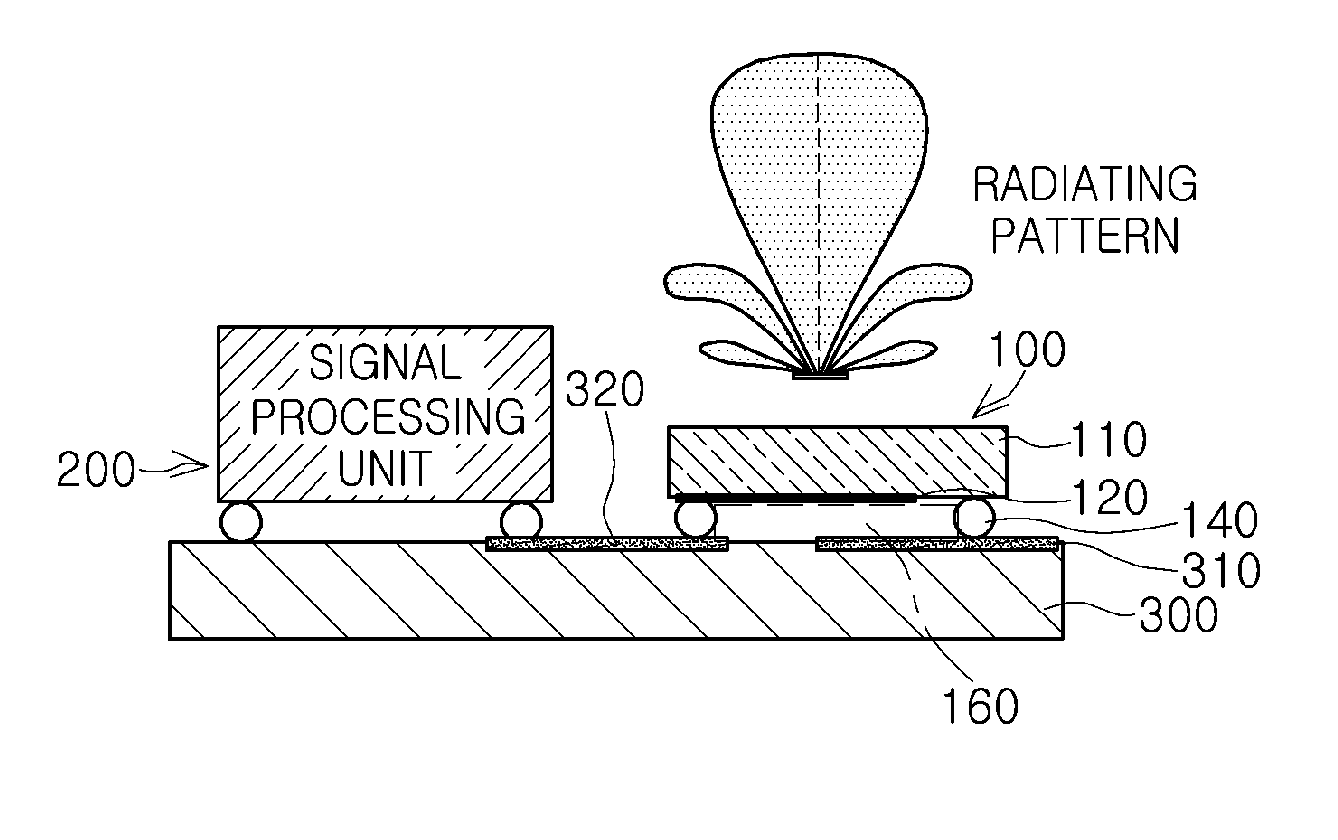
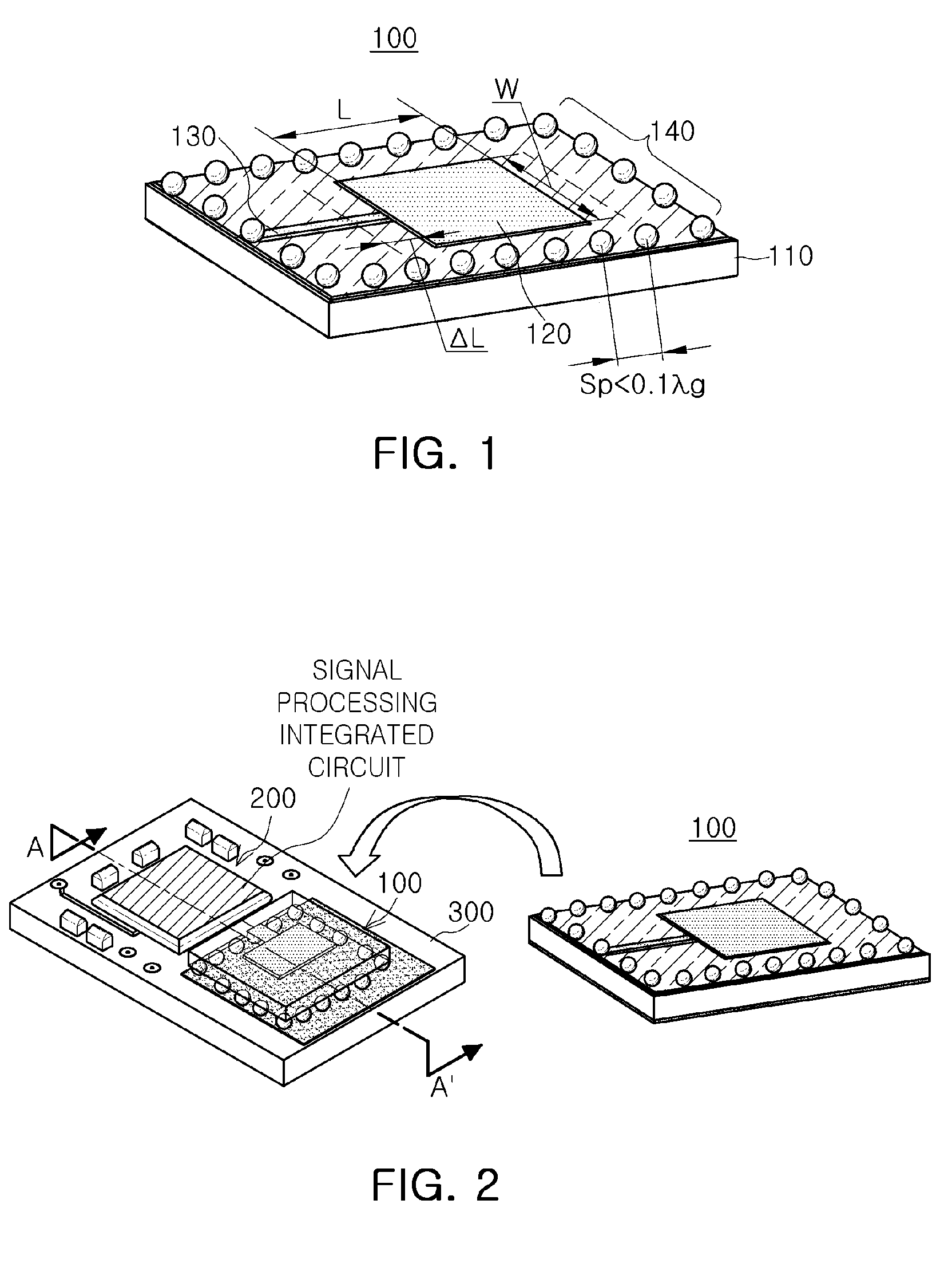
[0030]FIG. 1 is a schematic configuration diagram of an antenna according to an embodiment of the present invention.

[0031]Referring toFIG. 1, an antenna 100 according to an embodiment of the present invention may include a substrate 110, an antenna pattern part 120, a feeding pattern part 130, and a solder ball group 140.

[0032]The substrate 110 may be formed of a di...


PUM


Abstract

There are provided an antenna and a front end module having an air cavity formed therein and shortening a connection distance with a signal processing module to improve radiation characteristics and facilitate a manufacturing process thereof, the antenna including a substrate having a preset mounting surface, an antenna pattern part formed on the mounting surface of the substrate and transmitting and receiving a signal within a preset frequency band, and a solder ball group having a plurality of solder balls formed on the mounting surface of the substrate to fix the substrate to an external circuit board and disposed at preset intervals around the antenna pattern part to form an air cavity.

Description

CROSS-REFERENCE TO RELATED APPLICATIONS[0001]This application claims the priority of Korean Patent Application No. 10-2012-0149940 filed on Dec. 20, 2012, in the Korean Intellectual Property Office, the disclosure of which is incorporated herein by reference.BACKGROUND OF THE INVENTION[0002]1. Field of the Invention[0003]The present invention relates to an antenna and a front end module able to transmit and receive a signal within a millimeter wave band.[0004]2. Description of the Related Art[0005]Recently, domestic and international research into next-generation Wi-Fi networks (80.11b / a / g / n) in a 2.4 GHz / 5 GHz frequency band and 801.11ad (WiGig) in a 60 GHz band (millimeter wave (mmWave)) able to transmit large-capacity data has been actively undertaken.[0006]Generally, in the case of the foregoing 801.11b / a / g / n network standard, an antenna that transmits and receives a signal is generally installed on the outside of the module.[0007]However, in the case of the 801.11ad network sta...

Claims


Application Information

Patent Timeline
Patent Type & Authority Patents(United States)
IPC IPC(8): H01Q1/38H01Q1/22H01Q9/04
CPCH01Q1/2283H01Q9/0407H01Q1/36H01Q1/38
Inventor HAN, MYEONG WOOSONG, YOUNG JEANWON, JUN GOOIIZUKA, SHINICHIKIM, YOUN SUKKIM, KI JOONG
Owner SAMSUNG ELECTRO MECHANICS CO LTD
Why Eureka
Try Eureka