Acoustic dampener

a dampener and acoustic energy technology, applied in the direction of flooring, building components, flooring insulation, etc., can solve the problems of increasing the cost of a flooring system, requiring additional labour time, and reducing the sound transmission, so as to reduce the acoustic energy transmission, low component cost, and low installation skill level

Active Publication Date: 2016-02-02
JAMES HARDIE TECH LTD
View PDF14 Cites 0 Cited by
  • Summary
  • Abstract
  • Description
  • Claims
  • Application Information

AI Technical Summary

Benefits of technology

[0012]The advantage of the present invention is that it provides an acoustic dampener for use in building construction, which removes or decouples contact between flooring sheet components and substructure components thereby reducing acoustic energy transmission, while maintaining low component cost and low installation skill level.
[0013]In the following the description the first and second ends of each side arm are also referred to as the distal edge and proximal edge of each side arm, wherein each side arm extends from the proximal edge at the predetermined angle from the side edge of the base to form the channel formation. Each flange within the pair or flanges extend substantially orthogonally from respective distal edges of the side arms.
[0014]It is acknowledged that the term ‘comprise’ may, under varying jurisdictions be provided with either an exclusive or inclusive meaning. For the purpose of this specification, the term comprise shall have an inclusive meaning that it should be taken to mean an inclusion of not only the listed components it directly references, but also other non-specified components. Accordingly, the term ‘comprise’ is to be attributed with as broad an interpretation as possible within any given jurisdiction and this rationale should also be used when the terms ‘comprised’ and / or ‘comprising’ are used.
[0015]In one embodiment of the invention the channel formation is configured to receive a batten.
[0016]In a further embodiment of the invention the or each flange is configured to retain a batten within the channel.
[0017]According to the invention there is also provided a floor structure comprising an acoustic dampener of the invention securable to a structural substrate, a batten disposed within the channel formation and flooring material secured to the batten.

Problems solved by technology

Although some reduction in sound transmission may occur, it is limited because of the direct connection of the flooring sheets to the flooring substructure.
These multiple layer systems, such as those employing two or more layers of paper faced gypsum boards, increase the cost of a flooring system both by increasing the amount of materials used for a given floor area and by requiring additional labour time for installation.

Method used


Image

  • Acoustic dampener
  • Acoustic dampener
  • Acoustic dampener

Examples


example one

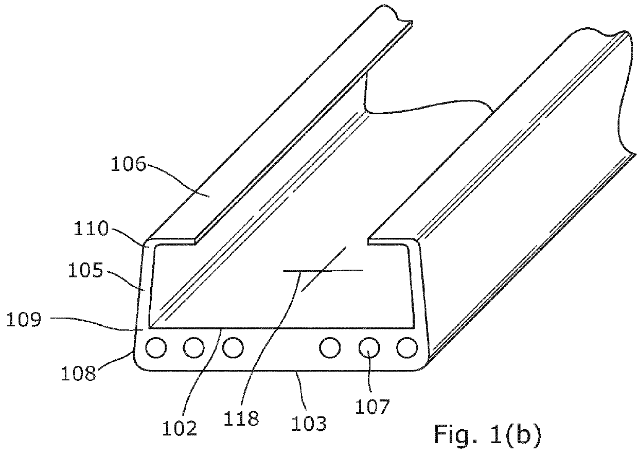
[0087]This example demonstrates the improvement in acoustic performance achievable using acoustic dampeners according to one embodiment of the invention. In this example, a timber structural substrate, in the form of a flooring subframe, is constructed in the normal way with 100×75 mm bearers supporting 100×50 mm joists spaced at 600 mm centres. This timber structural substrate forms the base of the flooring system in a building construction.

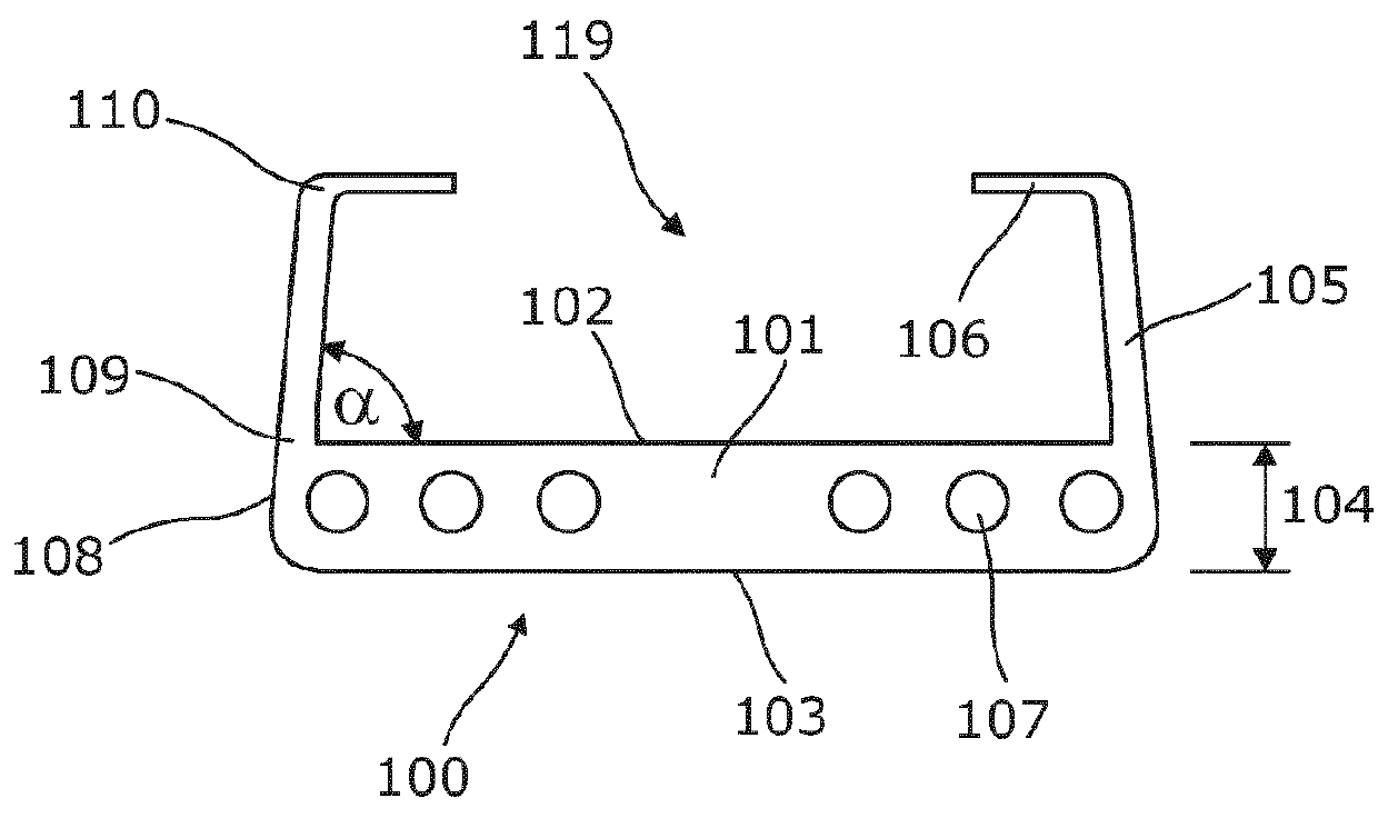
[0088]In this example, acoustic dampeners of the invention are in the form of extruded sections 3 meters in length. Each acoustic dampener is made from an EPDM rubber having a Shore hardness of 45-50. The acoustic dampener has a base 76 mm wide at its widest point, with the lower corners radiused at a 2 mm radius. The second surface of the base has a series of recessed channels 5 mm wide, 6 mm deep and evenly spaced 5 mm apart across the second surface. Each channel termination within the thickness is radiused at about a 2.5 mm radius. A centre ...

example 2

[0096]In this embodiment of the invention, a timber subframe is constructed in the normal way using 100×75 mm timber bearers and 100×50 mm joists at 600 mm centres.

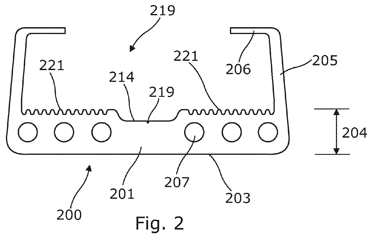
[0097]Acoustic dampeners are screw fixed to the joists. In this example, each acoustic dampener is formed from an EPDM rubber having a Shore hardness of 50-55.

[0098]In this example, each acoustic dampener is in the form of an extruded section 10 meters in length and supplied in roll form that can be cut to the required lengths. Where there is a section too short to fit the desired location, another length can be cut from another roll to make up the difference. The leading end of the new length can be butted up against the trailing end of the preceding length to ensure continuity of performance along the length of the joist.

[0099]The acoustic dampener has a base 77 mm wide at its widest point, with the lower corners radiused at a 2 mm radius. The thickness of the base has a series of 6 circular cross-section apertures each...


PUM

PropertyMeasurementUnit
angleaaaaaaaaaa
heightaaaaaaaaaa
heightaaaaaaaaaa

Abstract

An acoustic dampener (100) comprising a base member (101) having a first surface (102) and a second surface (103), the first surface (102) and the second surface (103) are spaced apart from each other defining a thickness (104) therebetween. The acoustic dampener (100) further comprising a pair of side arms (105), each having a first end (109) and a second end (110). Each side arm (105) is attached to the base member (101) at its first end (109) at a predetermined angle. The side arm (105) extends from the base member (101) to form a channel formation (119) to receive a batten. A flange (106) extends substantially orthogonally from the second end (110) of each side arm (105) for retaining a batten within the channel formation (119).

Description

FIELD OF THE INVENTION[0001]The present invention relates to dampening of acoustic energy and in particular to acoustic dampeners suitable for use in dampening of acoustic energy transmissions in buildings.[0002]The invention has been developed primarily for use as acoustic dampeners suitable for use in acoustic dampening of flooring systems in buildings and will be described hereinafter with reference to this application. However, it will be appreciated that the invention is not limited to this particular field of use.BACKGROUND OF THE INVENTION[0003]Any discussion of the prior art throughout the specification should in no way be considered as an admission that such prior art is widely known or forms part of the common general knowledge in the field.[0004]Strip form acoustic insulation for use between sheet building products and a structural building substructure, such as timber joists on a frame, are known. They are generally arranged between a flooring sheet and a flooring substr...

Claims


Application Information

Patent Timeline
Patent Type & Authority Patents(United States)
IPC IPC(8): E04B1/82E04F15/20
CPCE04F15/20Y10T29/4957
Inventor PAGONES, PETERGLEESON, JAMES
Owner JAMES HARDIE TECH LTD
Why Eureka
Try Eureka