
Measuring method for linear stage

a linear stage and measurement method technology, applied in the field of measuring methods, can solve the problems of linear stage straightness error, laser interferometer cannot meet the demand of on-line instantaneous linear stage measurement, and the mentioned measurement devices are not suitable for installation on the precise positioning machinery for on-line measurement, etc., to achieve the effect of simple and rapid calculation

Active Publication Date: 2016-02-09
METAL INDS RES & DEV CENT
View PDF1 Cites 4 Cited by
  • Summary
  • Abstract
  • Description
  • Claims
  • Application Information

AI Technical Summary

Benefits of technology

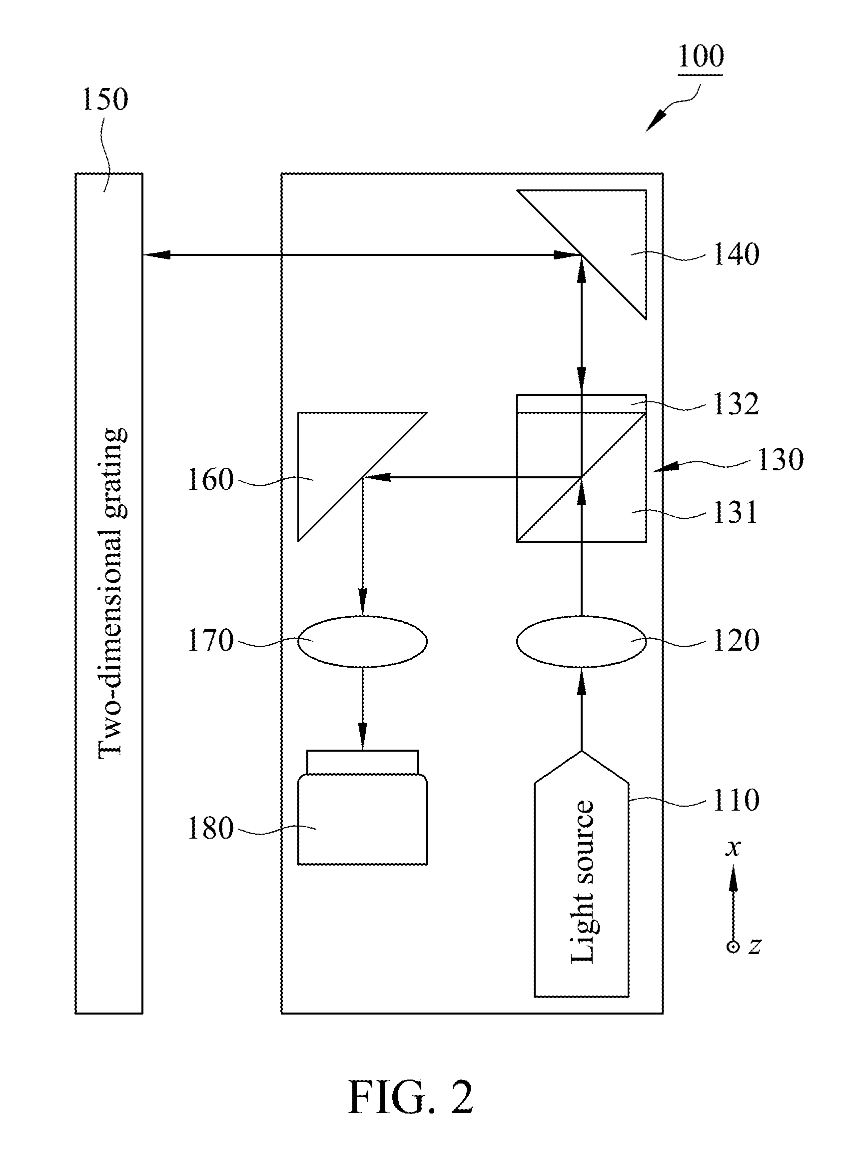
The present invention is a measuring device for linear stages that uses a light source, two-dimensional grating, quadrant photodiode, and processor to calculate the displacement and straightness error of the linear stage. The device can measure the displacement volume and straightness error of the linear stage in real-time, allowing for instantaneous control. The measurement is done by analyzing the sensing signals generated by the quadrant photodiode, which is in the light path of the reflection light from the two-dimensional grating. The method is simple and rapid, making it suitable for on-line measurement.

Problems solved by technology

However, the mentioned measurement devices are not suitable to install on precise positioning machinery for on-line measurement as a result of heavy overall structure.
However, the laser interferometer is only used for calculating and correcting in off-line mode so the laser interferometer can not satisfy the demand of on-line instantaneous measurement of linear stage.
Eventually, a straightness error of linear stage is obtained.

Method used


Image

  • Measuring method for linear stage
  • Measuring method for linear stage
  • Measuring method for linear stage

Examples


Embodiment Construction

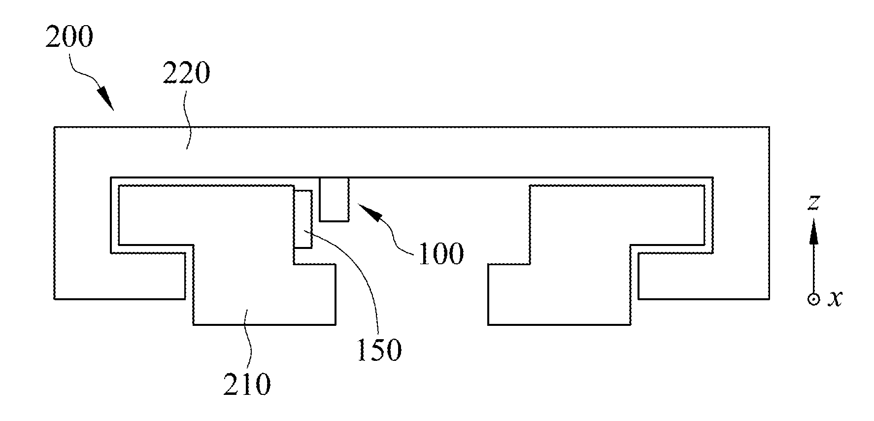
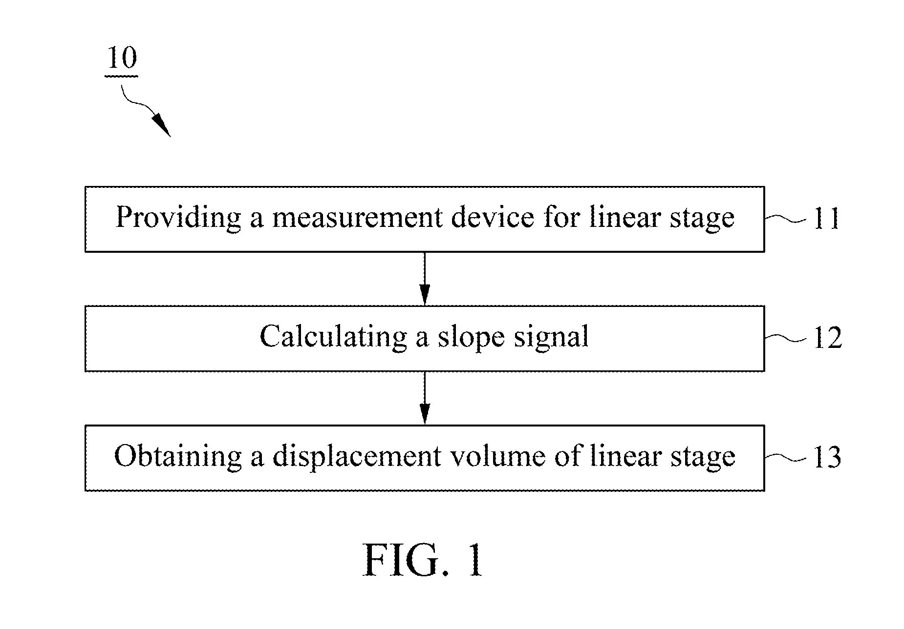
[0015]With reference to FIGS. 1, 2 and 3, a measuring method for linear stage 10 and a measurement device 100 for linear stage of the present invention used for measuring a displacement volume of a linear stage 200 are illustrated in mentioned figures. With reference to FIG. 1, provides the measurement device 100 for linear stage in a step 11 of providing the measurement device for linear stage. With reference to FIG. 2, in this embodiment, the measurement device 100 for linear stage includes a light source 110, a collimator lens 120, a polarization-splitting device 130, a first reflection device 140, a two-dimensional grating 150, a second reflection device 160, a focal lens 170 and a quadrant photodiode 180.

[0016]With reference to FIG. 2, the light source 110 provides an incident light, preferably, the light source 110 is a laser light. The collimator lens 120 disposed in the light path of the incident light is located between the light source 110 and the polarization-splitting de...


PUM


Abstract

A measuring method for linear stage used for measuring a displacement volume of a linear stage includes a light source, a two-dimensional grating, a quadrant photodiode and a processor. The light source provides an incident light, and the two-dimensional grating is disposed in light path of the incident light and reflects the incident to form a reflection light. The quadrant photodiode is disposed in light path of the reflection light and receives the reflection light for generating a plurality of sensing signals. The processor receives the sensing signals and utilizes the sensing signals to calculate a slope signal by a slope signal equation of the two-dimensional grating and an initial position signal and an end position signal by a position signal equation of the two-dimensional grating. The processor obtains the displacement volume of the linear stage by the slope signal, the initial position signal and the end position signal.

Description

FIELD OF THE INVENTION[0001]The present invention is generally relating to a measuring method, particularly relates to the measuring method for linear stage.BACKGROUND OF THE INVENTION[0002]Conventional measurement and positioning for linear stage constantly performs mensuration by utilizing a laser interferometer, an optical scale, an autocollimator or an electronic level. However, the mentioned measurement devices are not suitable to install on precise positioning machinery for on-line measurement as a result of heavy overall structure.[0003]Conventional measurement method of the laser interferometer utilizes a way of optical interference to proceed with off-line correction. The procedures of optical interference are: splitting a light beam, making two splitting light beams traveled in two different light paths to reach corresponding reflective mirrors, reflecting the light beams to reach an optical detector by reflective mirrors therefore producing interference pattern through pa...

Claims


Application Information

Patent Timeline
IPC IPC(8): G01B11/14G01B11/04G01B11/02
CPCG01B11/04G01B11/026G01B11/002
Inventor TSAI, HSIU-ANAN, NAI-CHUN
Owner METAL INDS RES & DEV CENT
Learn More