

Battery block and manufacturing method therefor
a technology of battery block and manufacturing method, which is applied in the field of battery block, can solve the problems of affecting the performance of storage batteries, accelerating cell degradation, and large storage battery capacity, and achieves high dimensional precision in portions, limited vibration of the accommodated cells, and high dimensional precision
- Summary
- Abstract
- Description
- Claims
- Application Information
AI Technical Summary
Benefits of technology
Problems solved by technology
Method used
Image

Examples
experimental examples
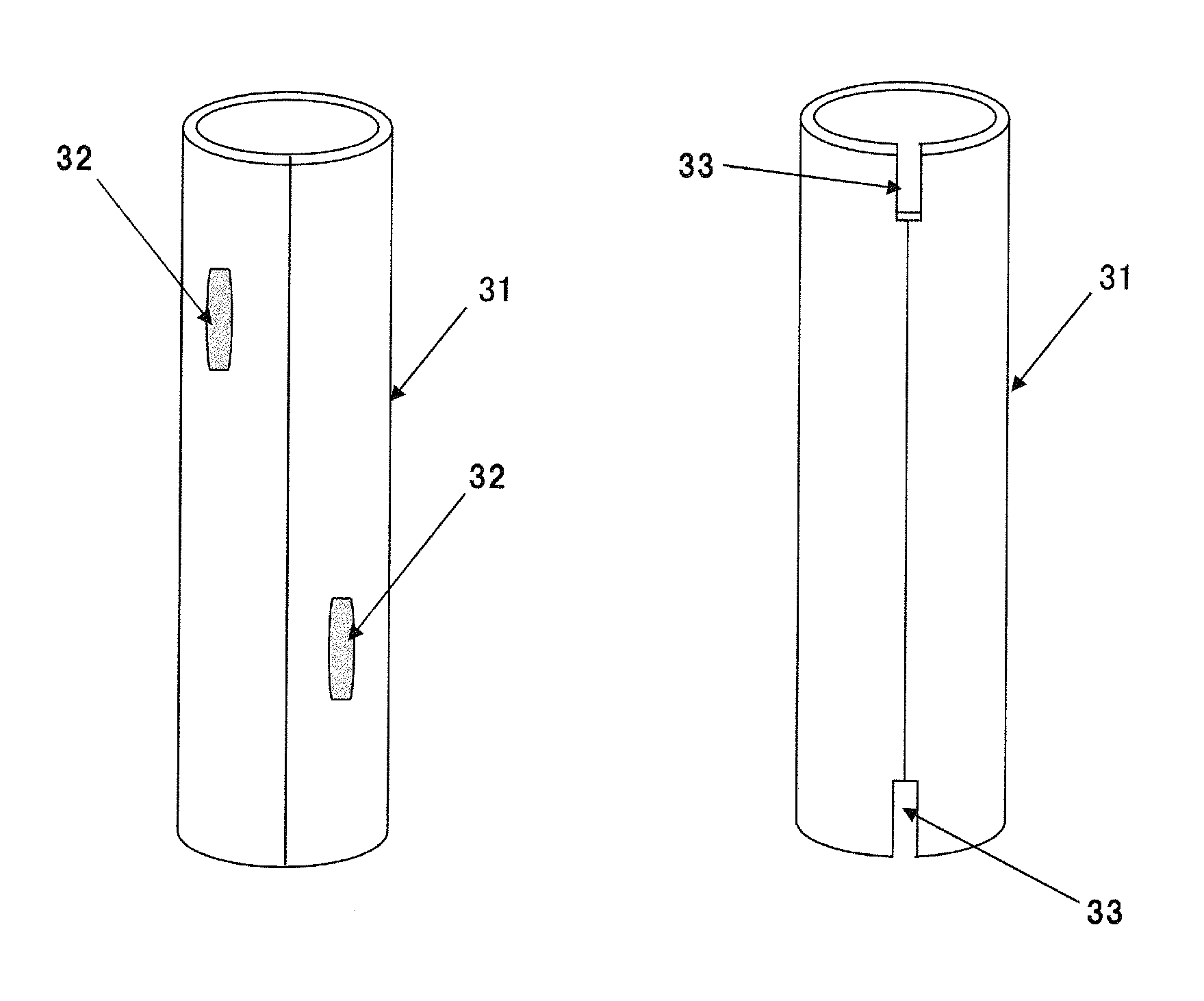
[0060]Two cylindrical aluminum pipes (inner diameter: 18.2 mm, length: 70 mm, and wall thickness: 0.4 mm) were provided. The two aluminum pipes were joined together. Joining was effected by laser welding in Experimental Examples 1 to 4, by flux joining in Experimental Example 5, and by means of an adhesive in Experimental Example 6.
[0061]In Experimental Example 1, the lengthwise central 50 mm part of the contact part between the two cylindrical aluminum pipes was subjected to laser welding. Similarly, the lengthwise central 25 mm part was subjected to laser welding in Experimental Example 2, the lengthwise central 12.5 mm part in Experimental Example 3, and the lengthwise ends in Experimental Example 4.
[0062]The types of the method of joining two cylindrical pipes and the states of joint (joint length, ratio of joint length, joint width, and joint area) are summarized in Table 1.
[0063]
TABLE 1JoiningmethodJoint lengthJoint ratioJoint widthJoint areaEx. 1Laser50 mm71%1 mm 50 mm2Ex. 2L...
PUM
| Property | Measurement | Unit |
|---|---|---|
| thickness | aaaaa | aaaaa |
| diameter | aaaaa | aaaaa |
| thickness | aaaaa | aaaaa |
Abstract
Description
Claims
Application Information