Method and control unit for adapting an upper headlight beam boundary of a light cone

a control unit and light cone technology, applied in the direction of vehicle position/course/altitude control, process and machine control, instruments, etc., can solve the problems of blinding of the driver of the other vehicle, the risk of low relative position being higher, etc., to achieve greater distance between the vehicle and the other vehicle, reduce blindness, and increase safety value

Active Publication Date: 2016-02-16
ROBERT BOSCH GMBH
View PDF19 Cites 2 Cited by
  • Summary
  • Abstract
  • Description
  • Claims
  • Application Information

AI Technical Summary

Benefits of technology

[0007]The present invention is based on the finding that the motion components of the motion of the host vehicle may be separated via a method according to the approach presented here. In this way, high-frequency, high-amplitude signal components may exert a smaller influence on the headlight beam boundary. This results in potential savings of computing power compared to direct adaptation of the headlight beam to a motion of the host vehicle, and potential savings of computing time, so that trailing in the signal processing may be reduced, which in turn allows a closer approximation of the headlight beam boundary to a glare limit. In addition, the roadway quality may also be ascertained by evaluating the time curve of the pitch rate or a value that is dependent on the pitch rate, such as the pitch acceleration or the pitch angle, or by evaluating the time curve of the roll rate or a value that is dependent on the roll rate, so that the beam angle of the headlights may thus be directly adapted and output even if no other vehicle is visible, or if, once another vehicle has been recognized, no time curve for a position of this vehicle is subsequently present. Instead of the pitch rate or roll rate, the object position in the image of a camera could also be evaluated, since the camera is fixedly installed in the vehicle and thus undergoes the same pitching or rolling motion as the vehicle, which is reflected in the position of the object in the image. Evaluating the pitch angle or roll angle, or the pitch rate or roll rate, is advantageous since, even before the other vehicle is encountered, a safety angle or safety value, for example, may be appropriately computed, and a headlight control system may reach a steady state more quickly. By evaluating the variation in the pitch angle or roll angle (and the pitch rate or roll rate) of the host vehicle, it is thus also possible, for example, to estimate the roadway quality and the changes in the pitch angle or roll angle which are thus expected.
[0027]In the detecting step, at least one additional time curve of a relative position of at least one feature of the additional other vehicle with respect to the vehicle may be detected in response to a recognition of at least one additional other vehicle in the detection range, and the upper headlight beam boundary may be adapted to that other vehicle which has the lower relative position of the feature of one of the other vehicles in the image. That other vehicle which has the feature with the lower relative position usually has the higher risk of blinding. A risk of blinding may be understood to mean a degree or a likelihood that a driver of the other vehicle is blinded by direct light of the headlight of the (host) vehicle when an unforeseen sudden increase in the relative angle occurs, for example due to driving over a pothole, and directs the light cone of the headlights directly onto the other vehicle. Operational safety may be increased by comparing multiple other vehicles, since the other vehicle with the highest risk (for blinding) at that moment is used as a reference for the maximum allowable upper headlight beam boundary.

Problems solved by technology

That other vehicle which has the feature with the lower relative position usually has the higher risk of blinding.
A risk of blinding may be understood to mean a degree or a likelihood that a driver of the other vehicle is blinded by direct light of the headlight of the (host) vehicle when an unforeseen sudden increase in the relative angle occurs, for example due to driving over a pothole, and directs the light cone of the headlights directly onto the other vehicle.

Method used


Image

  • Method and control unit for adapting an upper headlight beam boundary of a light cone
  • Method and control unit for adapting an upper headlight beam boundary of a light cone
  • Method and control unit for adapting an upper headlight beam boundary of a light cone

Examples


Embodiment Construction

[0041]In the following description of preferred exemplary embodiments of the present invention, identical or similar reference numerals are used for the elements having a similar action which are illustrated in the various figures, and a repeated description of these elements is dispensed with.

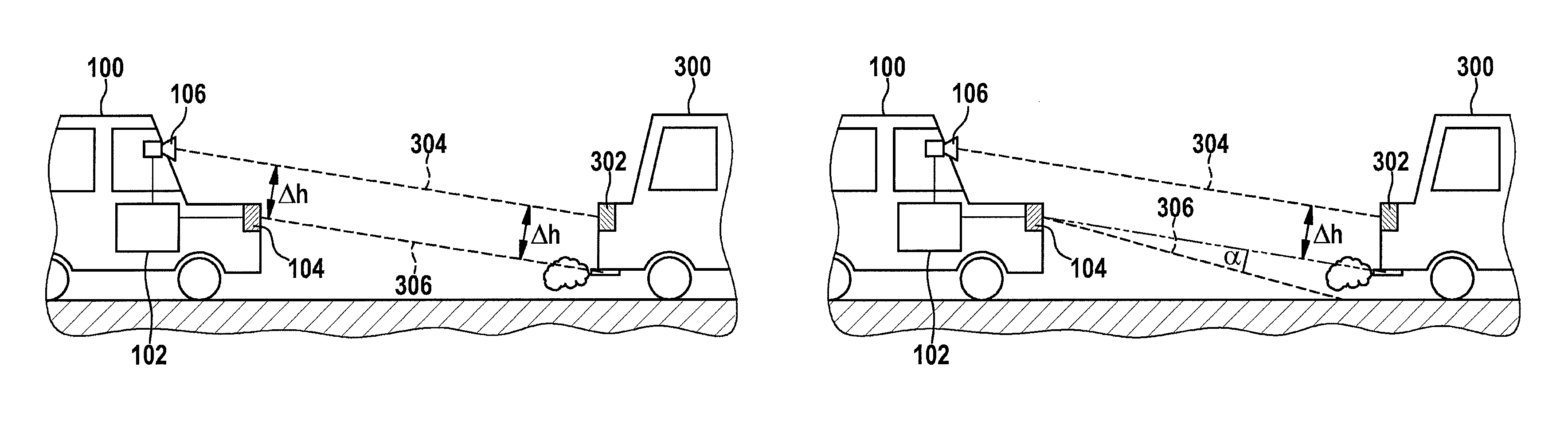
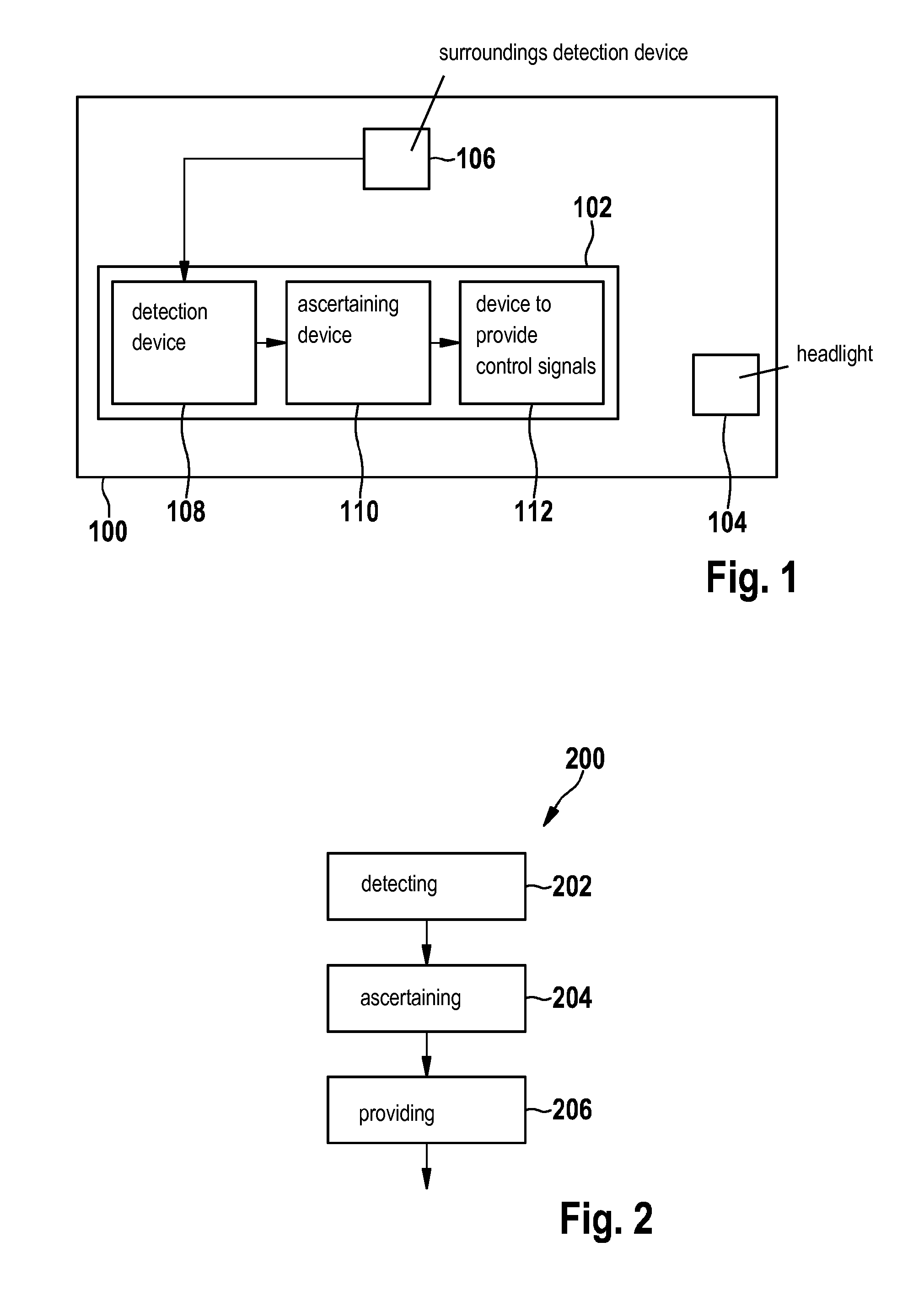
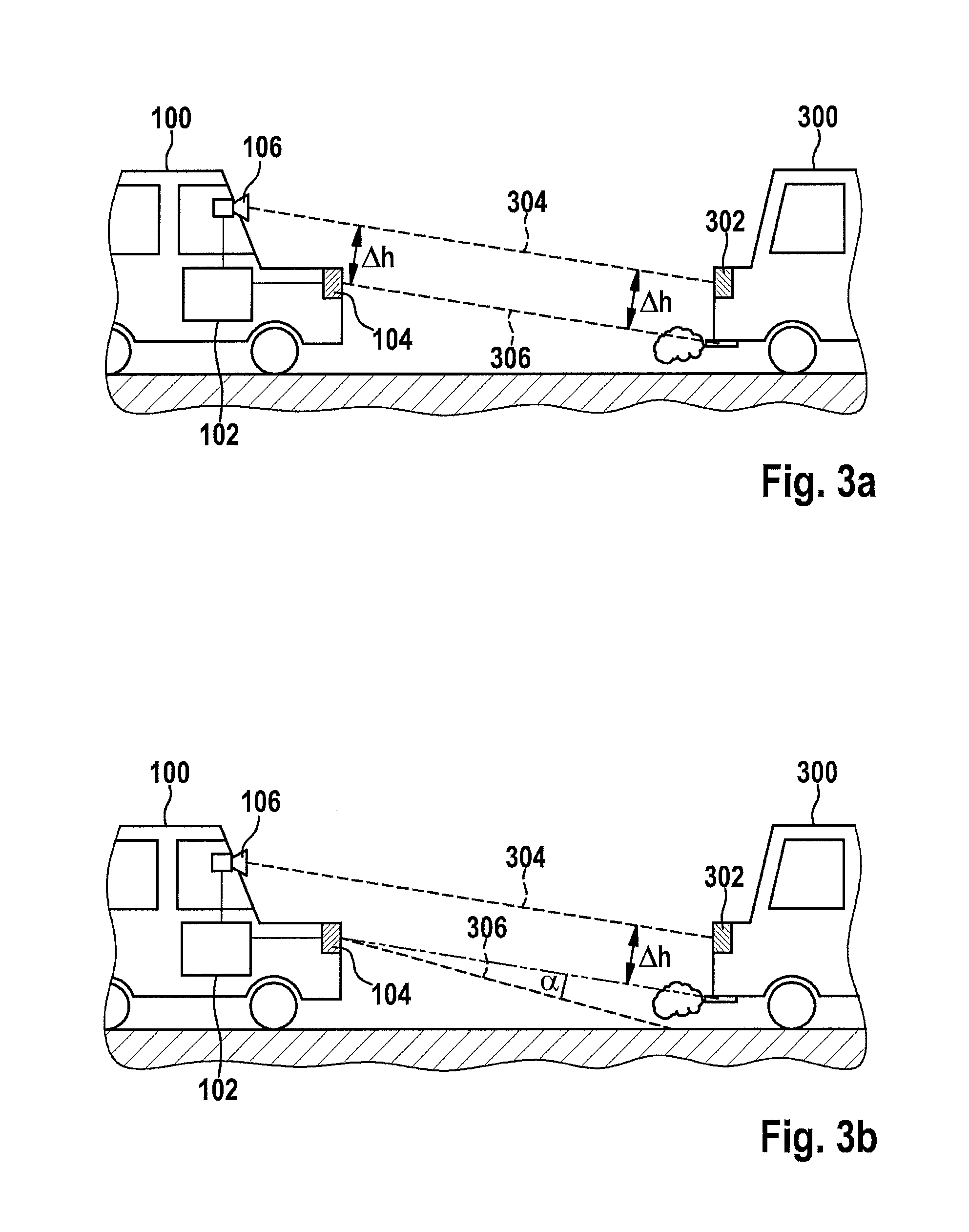
[0042]FIG. 1 shows an illustration of a vehicle 100 having a control unit 102 for adapting an upper headlight beam boundary of a light cone of at least one headlight 104 of vehicle 100 according to one exemplary embodiment of the present invention. Vehicle 100 has a surroundings detection device 106 and the at least one headlight 104. Surroundings detection device 106 is designed to provide information or an image concerning a detection range of surroundings detection device 106 for control unit 102. Control unit 102 is designed to provide a control signal for the at least one headlight 104 in response to the information. Control unit 102 has a detection device 108, a device for ascertaining 1...


PUM


Abstract

A method for adapting an upper headlight beam boundary of a light cone of at least one headlight of a vehicle. The method includes detecting a time curve of a pitch rate of the vehicle or a value that is dependent on the pitch rate and / or of a roll rate of the vehicle or a value that is dependent on the roll rate. The method also includes ascertaining an envelope curve and / or an amplitude of the time curve and / or an average value of the time curve. The method also includes providing a control signal for adapting the upper headlight beam boundary of the headlight beam.

Description

FIELD[0001]The present invention relates to a method for adapting an upper headlight beam boundary of a light cone of at least one headlight of a vehicle, a control unit for adapting an upper headlight beam boundary of a light cone of at least one headlight of a vehicle, and a corresponding computer program product.BACKGROUND INFORMATION[0002]Conventional headlight leveling control (HLC) of a headlight of a vehicle allows vertical swiveling of at least one beam-forming portion of the headlight or of a light source of the headlight in order to adapt a light cone of the headlight to a load situation of the vehicle. Automatic headlight leveling control may recognize a suspension state and load state of the vehicle via at least one chassis sensor. For example, the automatic headlight leveling control may compensate for pitching motions of the vehicle caused by acceleration forces such as stopping or braking, so that the light cone maintains a preset illumination range despite the pitchi...

Claims


Application Information

Patent Timeline
Patent Type & Authority Patents(United States)
IPC IPC(8): B60R22/00G06F7/00G05D3/00G06K9/00B60Q1/10B60Q1/08G05D1/00G06F17/00B60Q1/115E05F15/00
CPCB60Q1/115B60Q1/085B60Q1/10G06K9/00825B60Q2300/052B60Q2300/056B60Q2300/132B60Q2300/136B60Q2300/32B60Q2300/322B60Q2300/324B60Q2300/41B60Q2300/42G06V20/584
Inventor EHLGEN, TOBIASFOLTIN, JOHANNESMEISNER, ROBERT
Owner ROBERT BOSCH GMBH
Why Eureka
Try Eureka