
Using power fingerprinting (PFP) to monitor the integrity and enhance security of computer based systems

a computer based system and fingerprinting technology, applied in the field of power fingerprinting, can solve the problems of poor performance, unfavorable power fingerprinting performance, and complex implementation of pca, and achieve the effects of enhancing the integrity assessment of target system execution, improving the detection ability of pfp, and enhancing pfp performan

Active Publication Date: 2016-02-16
VIRGINIA TECH INTPROP INC
View PDF30 Cites 17 Cited by
  • Summary
  • Abstract
  • Description
  • Claims
  • Application Information

AI Technical Summary

Benefits of technology

[0012]It is therefore an object of the present invention to provide procedures for enhancing target system execution integrity assessment determined by power fingerprinting (PFP): by integrating PFP into the detection phase of comprehensive defense-in-depth security; by deploying a network of PFP enabled nodes; by executing untrusted devices with predefined inputs forcing a specific state sequence and specific software execution; by embedding module identification information into synchronization signaling; by combining signals from different board elements; by using malware signatures to enhance PFP performance; by automatic characterization and signature extraction; by providing secure signature updates; by protecting against side-channel attacks; performing real-time integrity assessment in embedded platform by monitoring their dynamic power consumption and comparing it against signatures from trusted code; by pre-characterizing power consumption of the platform and concentrating on trace sections carrying the most information about the internal execution status; by improving the ability of PFP to detect deviations from authorized execution in commercial embedded platforms.
[0017]Using malware signatures to enhance PFP performance, generalizing on existing battery monitoring technology.

Problems solved by technology

Once the traces from the execution of both sequences are captured and synchronized, LDA is used to find the optimal transformation vector W. It is expected that platform characterization using LDA will provide the best performance, given the availability of two known classes, but its implementations is more complex than PCA.
In this naive example, the performance of power fingerprinting is not encouraging, as there is barely any difference between the distributions, which substantially overlap.
This poor performance is expected considering the small differences in power consumption between the base and alternative scenarios.
Because perfect absolute prevention is not feasible, it is necessary to perform constant monitoring of the integrity of the systemResponse.
The different layers are intended to slow an adversary and make it progressively more difficult to breach a defensive layer without being noticed.
Even with trusted providers, there is the potential for foreign or disgruntled personnel to try to disrupt the operation and functionality of critical systems.
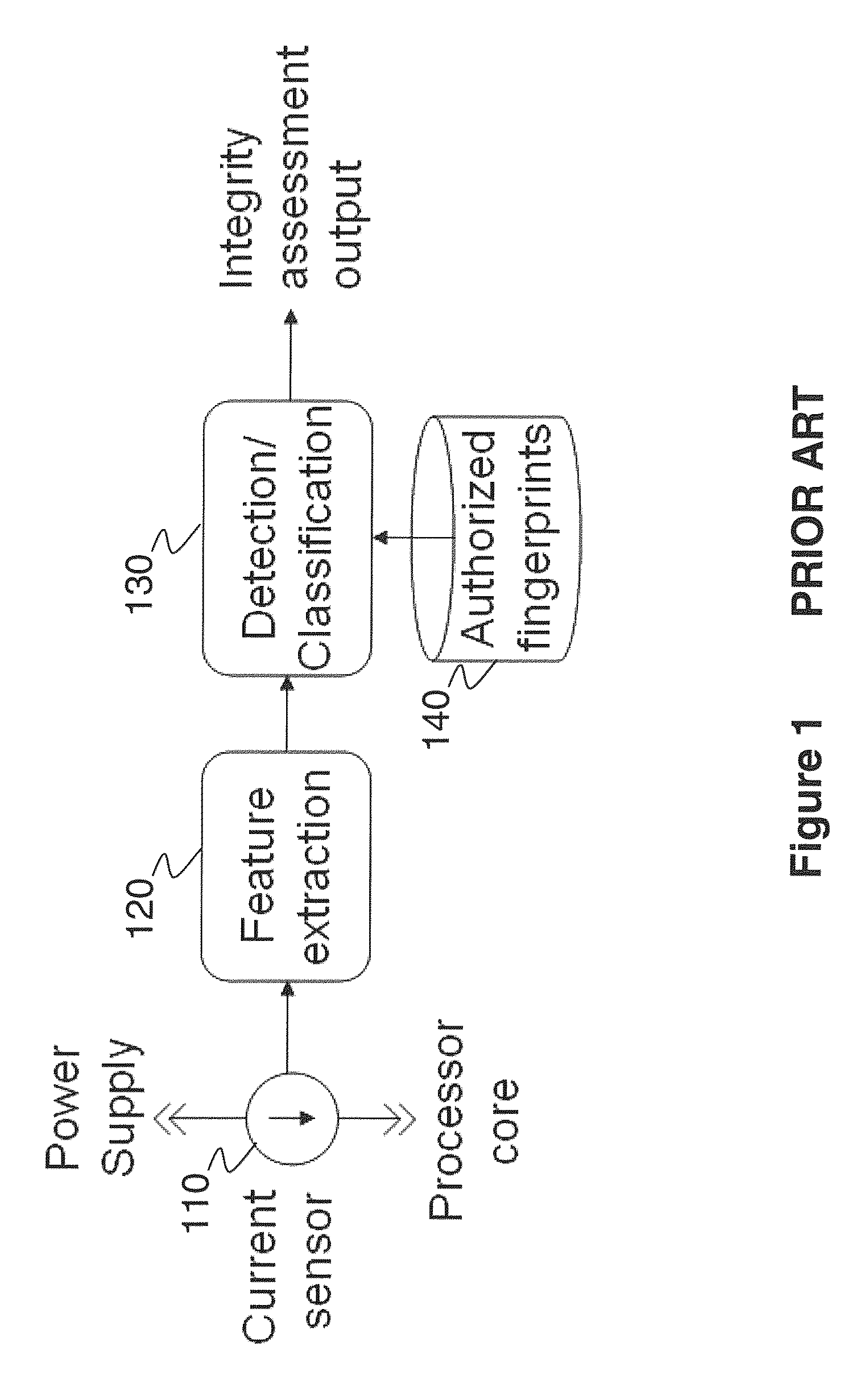
Furthermore, the fine-grained measurements of the power consumption provide significant visibility into the internal execution status of the device, making it extremely difficult for a modification to go unnoticed.
In many occasions however, such trusted implementation is not available.
Hardware components undergo an inevitable aging process, which is accelerated by operation in harsh environments or when the systems operate under continuous environmental stress.
The latter synchronization is more difficult to achieve and the process is facilitated by embedding in the routine itself a trigger, or identifier, that informs the PFP monitor the execution of a specific routine.
More bit transitions result in higher current drain.
Different from automatic testing, however, PFP characterization is only concerned with “observing” several execution instances of different modules and does not try to evaluate any requirements or properties.
Without this automatic approach, it would take too long to characterize and extract the unique signatures from complex systems (i.e. commercial systems) to be used in power fingerprinting.
This is a relatively risky approach, because a valid execution state can be reached that has not been characterized and, hence, is flagged as an anomaly.
Fortunately, most of the elements necessary for the scaffolds overlap in functionality with the traditional scaffolds for automatic testing (e.g. unit, integration, and system testing), adding only a little bit of extra work.
For highly integrated systems, this may represent a challenge.
There is no known effective procedure to determine the optimal discriminatory features for a given problem.
In practical systems, however, this is not feasible and a finite, practical PFA level must be determined.
It is important to note, however, that even if a potential attacker acquires the signatures, it would be still very difficult to match the signatures perfectly while carrying on malicious behavior.
The main challenge in PFP signature updating is authentication (i.e. making sure the sender is an authorized entity and that the signature itself is correct and has not been tampered with or altered in any way).
For example, if not properly authenticated, the update process can be disrupted by a man-in-the-middle attack.
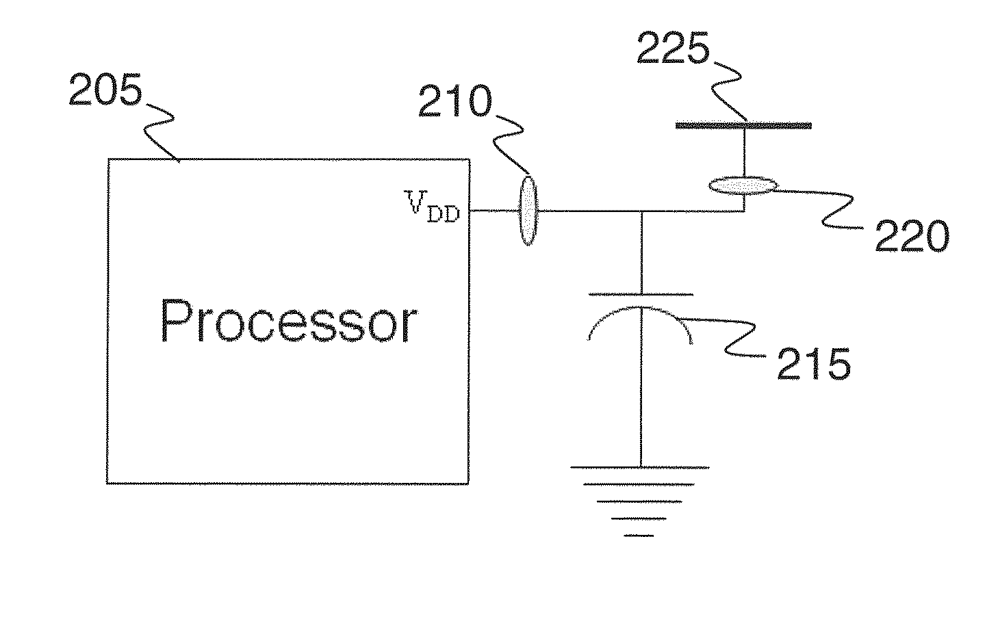
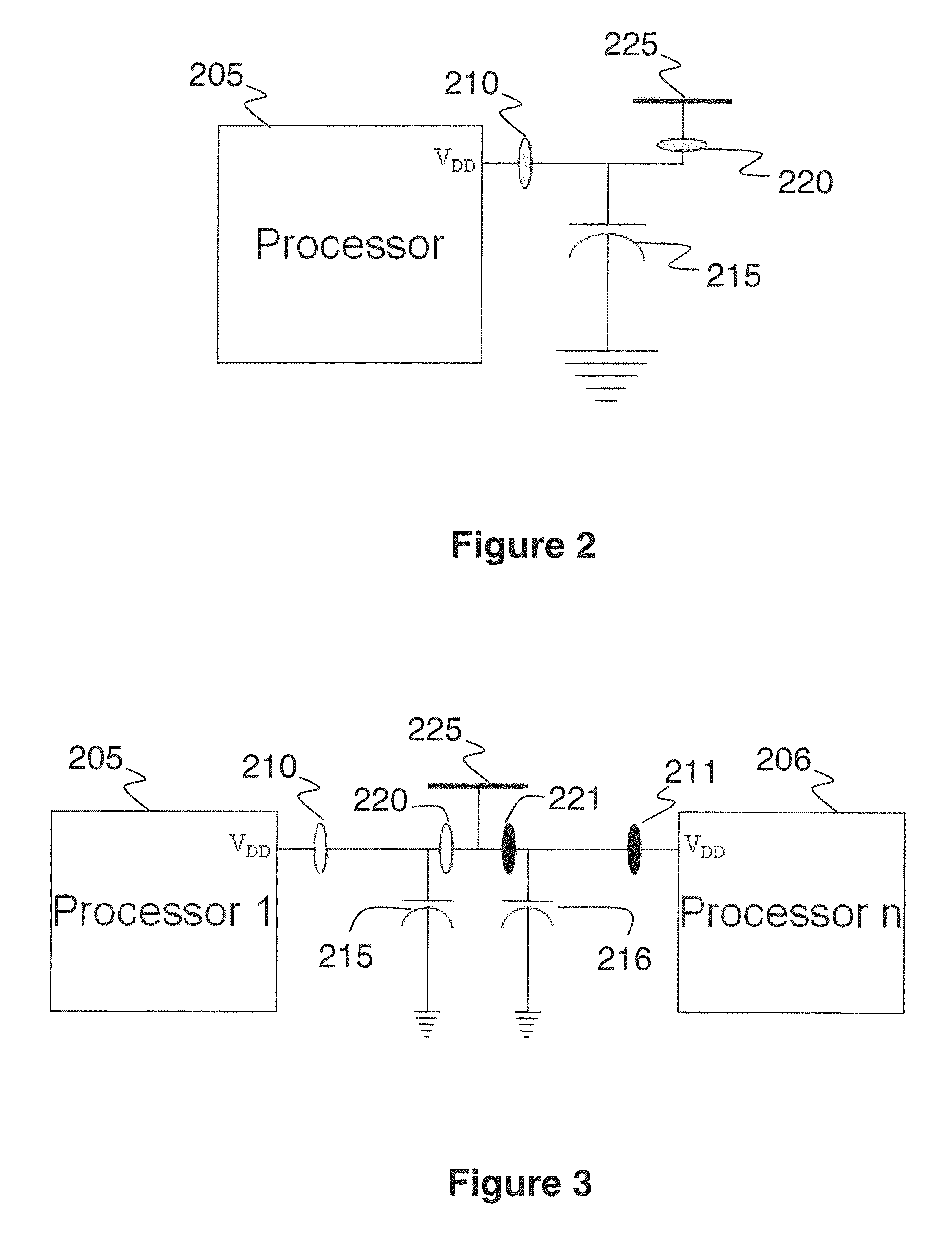
The power management chip can be as simple as a voltage regulator, but for most commercial processors used in modern smart-phones, the power management chips are much more complex.
It is important to note that the solutions here described are not intended to prevent attackers from carrying on side channel attacks against our target systems.

Method used


Image

  • Using power fingerprinting (PFP) to monitor the integrity and enhance security of computer based systems
  • Using power fingerprinting (PFP) to monitor the integrity and enhance security of computer based systems
  • Using power fingerprinting (PFP) to monitor the integrity and enhance security of computer based systems

Examples


Embodiment Construction

[0067]Power fingerprinting (PFP) is a technique that enables an external monitor to assess the execution integrity of a cyber system. PFP relies on the execution status information carried by the dynamic power consumption of a processor. Using this information, along with pre-characterized signatures from trusted references, PFP is able to determine execution integrity in target systems. For practical application of PFP, it is necessary to implement specific apparatus and follow specific procedures to provide an effective monitoring solution. In this work, we describe various procedures for improving the operation, effectiveness, usability, and performance of a PFP monitoring solution.

Applying PFP to Detect Software Modifications in Smart Phones and Other Embedded Devices.

[0068]Cyber security has become a critical element for national security. Microprocessors are ubiquitous in almost every aspect of modern life. Technology developments in the information technology areas are moving...


PUM


Abstract

Procedures are described for enhancing target system execution integrity determined by power fingerprinting (PFP): by integrating PFP into the detection phase of comprehensive defense-in-depth security; by deploying a network of PFP enabled nodes executing untrusted devices with predefined inputs forcing a specific state sequence and specific software execution; by embedding module identification information into synchronization signaling; by combining signals from different board elements; by using malware signatures to enhance PFP performance; by automatic characterization and signature extraction; by providing secure signature updates; by protecting against side-channel attacks; performing real-time integrity assessment in embedded platform by monitoring their dynamic power consumption and comparing it against signatures from trusted code, including pre-characterizing power consumption of the platform by concentrating on trace sections carrying the most information about the internal execution status; by using PFP from sequence of bit transitions to detect deviations from authorized execution of software in a digital processor.

Description

CROSS-REFERENCE TO RELATED APPLICATIONS[0001]This application is a national-stage Patent Cooperation Treaty (PCT) filing from PCT / US2011 / 059244 filed Nov. 3, 2011, and this application claims priority to U.S. Provisional Applications 61 / 409,670 filed Nov. 3, 2010 and 61 / 475,713 filed Apr. 15, 2011, and the complete contents of these applications is herein incorporated by reference.STATEMENT OF GOVERNMENT INTEREST[0002]This invention was made with government support under Contract Number CNS0910531 awarded by the National Science Foundation. The government has certain rights in the invention.BACKGROUND OF THE INVENTION[0003]1. Field of the Invention[0004]The present invention generally relates to power fingerprinting and more particularly to use of power fingerprinting as a technique for improving the security and monitoring the integrity of computer processing and software used on computer-based systems.[0005]2. Background Description[0006]In CMOS digital circuits, with every bit tr...

Claims


Application Information

Patent Timeline
Patent Type & Authority Patents(United States)
IPC IPC(8): G06F11/00G06F21/56G06F11/30G06F21/52
CPCG06F21/56G06F11/3062G06F11/3093G06F21/52G06F21/755G06F21/00G06F11/30G06F11/22G06F2221/033G06F2221/034G06F1/28G06F1/3206H04L9/3247
Inventor REED, JEFFREY H.AGUAYO GONZALEZ, CARLOS R.
Owner VIRGINIA TECH INTPROP INC
Learn More