Exhaust gas and gas scrubber fluid cleaning equipment and method

a technology of exhaust gas and scrubber fluid, which is applied in the direction of machines/engines, centrifugal force sediment separation, chemical/physical processes, etc., can solve the problems of inability to transport large amounts of waste materials, inability to clean up, and release of polluted scrubber fluid into the sea, so as to reduce the need for service and improve the efficiency of exhaust treatment procedures , the effect of reducing the need for process equipmen

Active Publication Date: 2016-02-23
ALFA LAVAL CORP AB
View PDF74 Cites 5 Cited by
  • Summary
  • Abstract
  • Description
  • Claims
  • Application Information

AI Technical Summary

Benefits of technology

[0009]According to aspects disclosed herein, the present invention provides a solution to the problems mentioned above by further improving environmental aspects of exhaust treatment procedures, improving the efficiency in exhaust treatment procedures, minimizing the need for service and diminishing problems with process equipment handling scrubber fluid.
[0011]The inventors have found that, by using a disc stack centrifugal separator the separation of the pollutant phase comprising pollutant particles from exhaust gas scrubber fluid is surprisingly efficient. The separation in such a separator is gentle enough to maintain particles agglomerated and at the same time efficient by providing high separation forces and short separation distances. The inventors have also found that lighter liquid organic residues in the scrubber fluid, such as oil, tend to adhere to denser solid particles in the fluid in a way that makes it possible, in the disc stack separator, to separate the oil and the particles as a pollutant phase which is denser than the scrubber fluid. Thus the scrubber fluid cleaning equipment does not have the same need for filters or other treatment steps and therefore improves the handling of the equipment by minimizing the need for service and replacement of key components. The inventors have proven that by applying a disc stack centrifugal separator on the scrubber fluid, a large part of the pollutant phase can be removed in concentrated form and without the addition of chemicals. Therefore the volume of waste material can also be kept low.
[0016]In one embodiment, the separator inlet is of a hermetic type. A hermetic inlet is sealed from the surroundings of the rotor and is arranged to be filled with scrubber fluid during operation. In a hermetic type of inlet the acceleration of the fluid is initiated at a small radius and gradually increased while the fluid leaves the inlet and enters the separation space. By using an inlet of a hermetic type, shear forces acting on the particle agglomerates in the scrubber fluid can be minimized, thereby improving the separation efficiency of the pollutant phase even further.
[0019]By incorporating a disc stack separator the need for filters or other treatment equipment is minimized. The use of the disc stack separator allows cleaned scrubber fluid to be directly fed from the first separator outlet to the scrubber without further need of treatment equipment between the separator and the scrubber. Examples of treatment equipment are different kinds of filters, separators etc.
[0021]In one embodiment, the exhaust gas cleaning equipment further comprises means for adjusting the acidity of the scrubber fluid in order to compensate for acidic components, such as SOx, in the exhaust gas which causes the scrubber fluid pH to decrease. In one embodiment, the means is adapted to keeping the acidity of the scrubber fluid above pH 6, in order to maintain particularly good separation performance.
[0023]In one embodiment, the exhaust gas cleaning equipment further comprises means for bleeding off part of the scrubber fluid to a bleed-off disc stack centrifugal separator. The means for bleeding off part of the scrubber fluid is, for example, arranged for bleeding off part of the polluted scrubber fluid, whereby the bleed-off separator may be arranged for separating at least a pollutant phase comprising pollutant particles and a cleaned scrubber fluid from said polluted scrubber fluid. As an alternative the means for bleeding off part of the scrubber fluid is arranged for bleeding off part of the cleaned scrubber fluid, whereby the bleed-off separator is arranged for removing any remaining pollutant particles in the cleaned scrubber fluid in order to allow it for overboard discharge. The bleed-off separator comprises a rotor enclosing a separation space with a stack of separating discs, a separator inlet for said part of the polluted scrubber fluid comprising pollutant particles extending into said separation space, a first separator outlet for cleaned scrubber fluid extending from said separation space, and a second separator outlet for the pollutant phase extending from said separation space. In one embodiment, the rotor of the bleed-off separator further encloses a conveyor screw which is arranged to be driven at a rotational speed differing from the rotational speed of the rotor so that to convey the pollutant phase, i.e. a separated phase with density higher than the cleaned scrubber fluid, towards the second separator outlet. In one embodiment, the second separator outlet is provided on a smaller radius than the outer radius of the separation space, and the conveyor screw arranged to convey the pollutant phase radially inwards and towards the second separator outlet. Due to this arrangement, the concentration of particles in the discharge can be very high, typically from about 95 to about 100% by volume, minimizing the amount of waste material being produced, while still maintaining a cleaned scrubber fluid that is able to fulfill regulations and that can be released into the environment with a minimal environmental impact.

Problems solved by technology

Also in this process polluted scrubber fluid is produced.
The release of such polluted scrubber fluid into the sea is unacceptable from an environmental point of view and is strictly regulated.
On the other hand it is expensive and undesirable to transport larger amounts of waste material to a harbour for disposal.
One problem is thus to improve the cleaning of the scrubber fluid.
A further problem is that particles in polluted scrubber fluid tend to adhere on process equipment and piping over time with the risk of a build up of soot scaling resulting in malfunctioning process equipment, sensors, transmitters and the like.
Equipment relying on filter technology also has the drawback in the need for surveillance, service and replacement of filter components.

Method used


Image

  • Exhaust gas and gas scrubber fluid cleaning equipment and method
  • Exhaust gas and gas scrubber fluid cleaning equipment and method
  • Exhaust gas and gas scrubber fluid cleaning equipment and method

Examples


Embodiment Construction

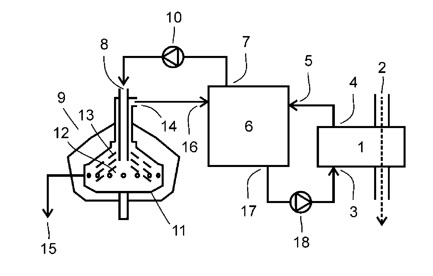
[0039]An exhaust gas cleaning equipment comprising a cleaning equipment for gas scrubber fluid is shown in FIG. 1. The exhaust gas scrubber 1 acts on an exhaust conduit 2 of a large diesel engine, such as the main engine of a ship. The scrubber is provided with a scrubber inlet 3 and a scrubber outlet 4 for scrubber fluid. The scrubber outlet 4 is connected to an inlet 5 of a buffer tank 6 for scrubber fluid. Starting from an outlet 7 the buffer tank 6 is provided with a cleaning circuit for scrubber fluid connected to a separator inlet 8 of a centrifugal separator 9 via a separator feed pump 10. The centrifugal separator 9 has a rotor 11 enclosing a separation space 12 which contains a stack of frustoconical separating discs 13 to which separation space the separator inlet 8 extends. The centrifugal separator 9 is further provided with a first separator outlet 14 for cleaned scrubber fluid, and a second outlet 15 extending from the separation space through the rotor in the form of ...


PUM

PropertyMeasurementUnit
pHaaaaaaaaaa
pHaaaaaaaaaa
turbidityaaaaaaaaaa

Abstract

Exhaust gas cleaning equipment including a gas scrubber and a scrubber fluid cleaning equipment for cleaning polluted scrubber fluid. The scrubber fluid cleaning equipment includes a centrifugal separator for separating at least a pollutant phase and a cleaned scrubber fluid from said polluted scrubber fluid. The centrifugal separator has a rotor enclosing a separation space with a stack of separating discs, a separator inlet for polluted scrubber fluid extending into said separation space, a first separator outlet for cleaned scrubber fluid extending from said separation space, and a second separator outlet for the pollutant phase extending from said separation space.

Description

BACKGROUND OF THE INVENTION[0001]The present invention relates to exhaust gas cleaning equipment comprising scrubber fluid cleaning equipment and a method for cleaning polluted scrubber fluid.[0002]The shipping industry of today strives to reduce harmful emissions, such as emissions originating from the combustion of fuel in the engine, in order to minimize the negative environmental impact and fulfill present and upcoming emission regulations.[0003]One part in this is the reduction in sulphuric oxide (SOx) emissions from ships. Sulphuric oxides are created in the combustion of fuels containing sulphuric residues. The amount of sulphuric oxides in exhaust gas can be reduced by exhaust gas cleaning, e.g. by using scrubbers. The process of cleaning exhaust gas with the aid of the mentioned scrubbers produces polluted scrubber fluid.[0004]Another object is the reductions in nitrogen oxides (NOx) emissions from marine engines. This can be done by implementing Exhaust Gas Recirculation (...

Claims


Application Information

Patent Timeline
Patent Type & Authority Patents(United States)
IPC IPC(8): B01D53/14B01D21/26F01N3/04C02F1/38C02F103/18F01N3/037
CPCB01D53/1425B01D21/262B01D2247/04B01D2257/302B01D2257/404C02F1/385C02F2103/18F01N3/037F01N3/04B01B1/00B01D47/00B01D53/14C02F1/38
Inventor KONIGSSON, STAFFANSUNDQUIST, LENA
Owner ALFA LAVAL CORP AB
Why Eureka
Try Eureka