Methods and apparatus of entangled photon generation using four-wave mixing

a technology of entangled photons and four-wave mixing, applied in the direction of optics, instruments, optical elements, etc., can solve the problems of linear momentum zero, linear wavevector and group velocities are poorly defined, linear wavevector and group velocities cannot be modeled with linear wavevectors,

Active Publication Date: 2016-02-23
NAT TECH & ENG SOLUTIONS OF SANDIA LLC
View PDF3 Cites 15 Cited by
  • Summary
  • Abstract
  • Description
  • Claims
  • Application Information

AI Technical Summary

Benefits of technology

[0013]We have developed a non-linear optical device that exhibits FWM. The device comprises an optical disk or ring microresonator fabricated from a material that exhibits an optical nonlinearity able to produce degenerate four-wave mixing (FWM) in response to a pump beam having a pump frequency in a spec

Problems solved by technology

However, the process must conserve both energy and momentum.
In a cylindrical system, however, the linear momentum is zero and the linear wavevector and group velocities are poorly defined, particularly for small resonator radii, such as r

Method used


Image

  • Methods and apparatus of entangled photon generation using four-wave mixing
  • Methods and apparatus of entangled photon generation using four-wave mixing
  • Methods and apparatus of entangled photon generation using four-wave mixing

Examples


example 1

[0059]This example is provided, in part, as a pedagogical aide to introduce the interpretation of our computational results, and it is provided, in part, as a basis for comparison to the surprising results described below in Example 2.

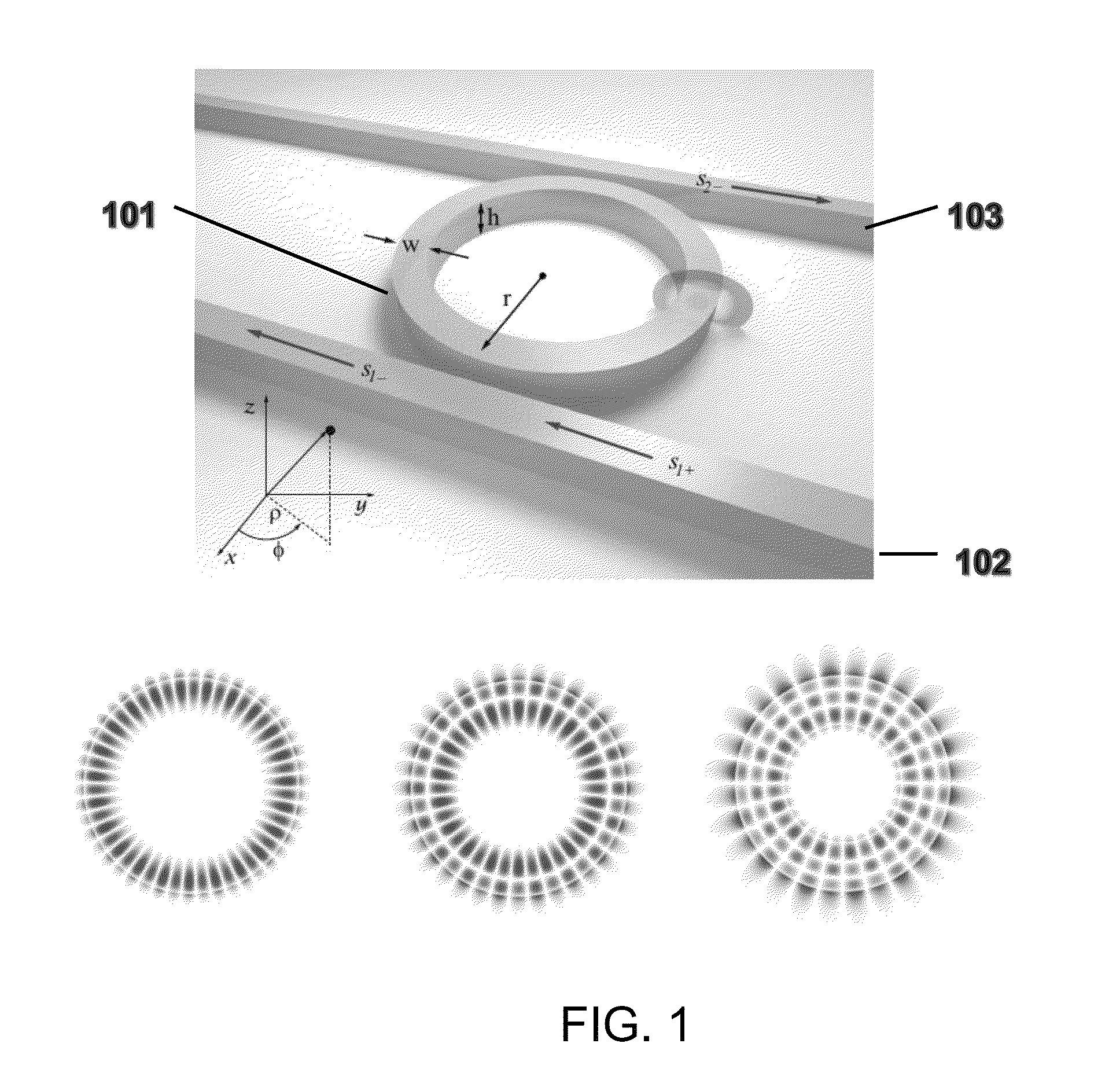
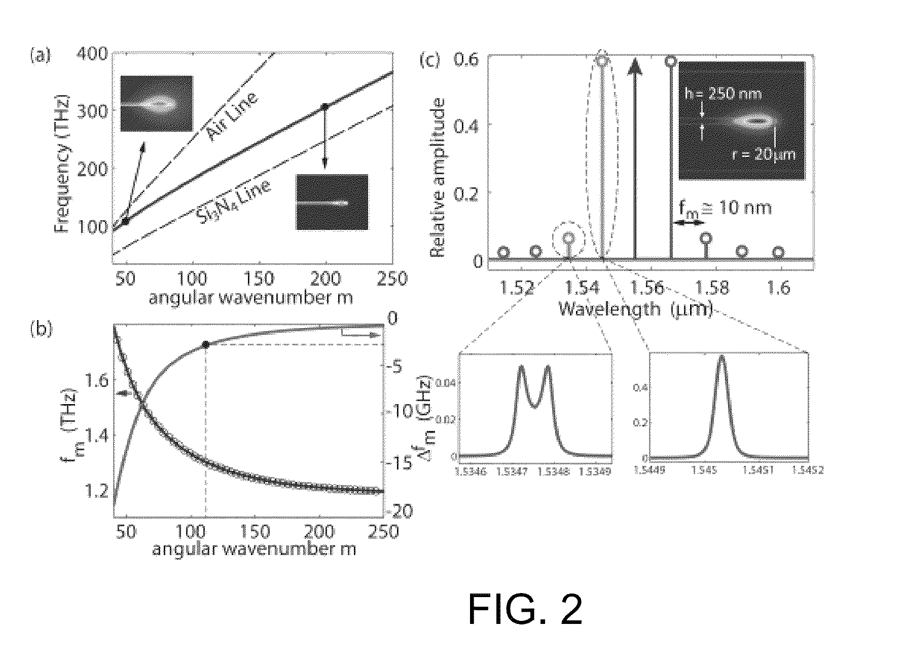
[0060]We modeled a silicon nitride disk, suspended in air, with a radius of 20 μm and a thickness of 250 nm. Silicon nitride was of interest because it is an important optical material whose spectral bandgap lies above the energy required for two-photon absorption at the 1550 nm communication wavelength.

[0061]FIG. 2a provides a plot of the frequency 2πωm of the fundamental TE-like mode of the disk as a function of the angular wavenumber m. This mode has odd vector symmetry about the z-axis. Physically, m represents the number of wavelengths that fit around the disk for a given mode. Small values of m correspond to low frequency and long wavelength; in that regime the mode field tends to spill out into the surrounding air. At larger values of m, however...

example 2

[0071]We modeled a silicon nitride ring of radius r=20 μm, clad with silicon dioxide, and of width w=1.1 μm and thickness h=750 nm.

[0072]FIG. 3 provides a set of plots analogous to those of FIG. 2, but with certain important qualitative differences readily apparent.

[0073]FIG. 3a provides a plot of the frequency 2πωm of the fundamental TE-like mode of the ring as a function of the angular wavenumber m. As seen in the figure, the mode frequency is again bounded by two light lines, which in this case correspond to the silicon dioxide medium and the silicon nitride medium. The mode frequency is seen to transition from one light line to the other as m increases.

[0074]FIG. 3b provides a plot of the first derivative (left-hand scale) and second derivative (right-hand scale) of 2πωm(m). Unlike the case of the thin disk as seen in FIG. 2b, the FSR as seen here does not decrease monotonically, but instead undergoes a steep decrease, followed by a shallow increase. Correspondingly, the graph o...


PUM


Abstract

A non-linear optical device is provided. The device comprises an optical disk or ring microresonator fabricated from a material that exhibits an optical nonlinearity able to produce degenerate four-wave mixing (FWM) in response to a pump beam having a pump frequency in a specified effective range. The microresonator is conformed to exhibit an angular group velocity minimum at a pump frequency within the specified effective range such that there is zero angular group velocity dispersion at the pump frequency. We refer to such a pump frequency as the “zero dispersion frequency”. In embodiments, excitation of the resonator by a pump beam of sufficient intensity at the zero-dispersion frequency causes the resonator to emit a frequency comb of entangled photon pairs wherein the respective frequencies in each pair are symmetrically placed about the zero-dispersion frequency.

Description

CROSS-REFERENCE TO RELATED APPLICATIONS[0001]This application claims priority from U.S. Provisional Patent Application Ser. No. 61 / 876,677, filed on Sep. 11, 2013 by R. Camacho under the title “Methods and Apparatus of Entangled Photon Generation Using Four-Wave Mixing,” which application is commonly owned herewith and the entirety of which is incorporated herein by reference.STATEMENT OF GOVERNMENT INTEREST[0002]This invention was developed under Contract DE-AC04-94AL85000 between Sandia Corporation and the U.S. Department of Energy. The U.S. Government has certain rights in this invention.ART BACKGROUND[0003]The generation of entangled photons is an essential element in current approaches to quantum information processing and quantum communication. In particular, it is often desirable to generate entangled photons having narrow spectral bandwidths to facilitate coupling to long-lived quantum memories or repeaters.[0004]Various physical mechanisms have been considered for generatin...

Claims


Application Information

Patent Timeline
IPC IPC(8): G02F1/35G02B27/00
CPCG02F1/3536G02B27/0012G02F2203/15G02F2203/56
Inventor CAMACHO, RYAN
Owner NAT TECH & ENG SOLUTIONS OF SANDIA LLC
Why Eureka
Try Eureka