Optically parametric oscillator

An optical parametric and parametric oscillation technology, which is applied in the field of optical waveguide theory, can solve the problems of limited band parametric optical output power, large optical loss, and low parametric optical output power, and achieve suppression of nonlinear optical effects and low pumping threshold. , to achieve the effect of high power

Active Publication Date: 2009-08-05
BEIJING JIAOTONG UNIV
View PDF0 Cites 14 Cited by
  • Summary
  • Abstract
  • Description
  • Claims
  • Application Information

AI Technical Summary

Problems solved by technology

This type of dispersion compensation technology is relatively simple, but it cannot form the oscillation of the parametric light with a frequency higher than that of the pump light, and can only output the parametric light in this band as idler light, which greatly limits the output power of the parametric light

Method used


Image

  • Optically parametric oscillator
  • Optically parametric oscillator
  • Optically parametric oscillator

Examples


Embodiment 1

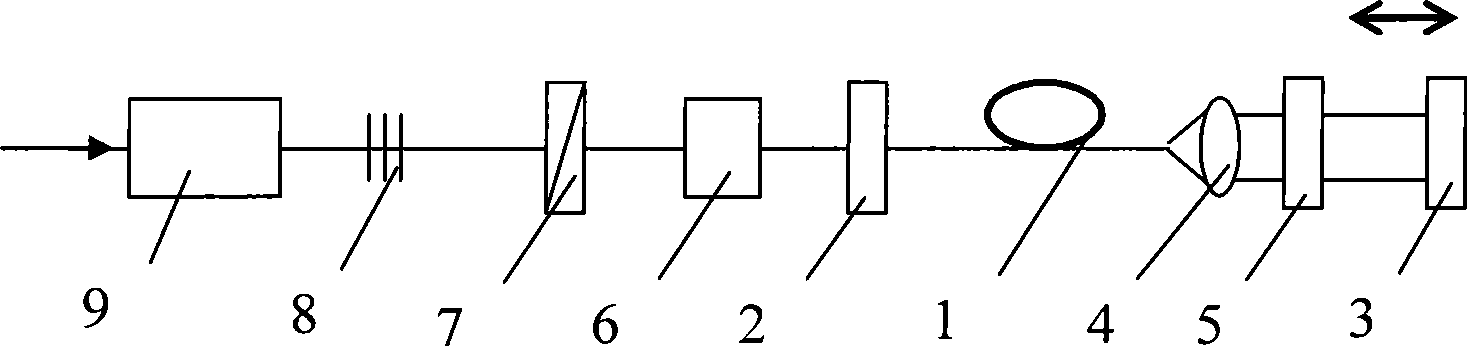
[0073] Such as figure 1 As shown, the optical parametric oscillator includes: a nonlinear microstructure 1 with double zero-dispersion wavelength, a high reflection mirror 2, an output mirror 3, a parametric oscillating light beam collimator 4, a line width compressor 5, and a pump optical coupler 6. λ / 2 phase retarder 7, pump optical power controller 8 and optical isolator 9.

[0074] The high reflection mirror 2 and the output mirror 3 form a resonant cavity, the double zero-dispersion wavelength nonlinear material 1 is placed in the resonant cavity, the parametric oscillating light beam collimator 4 is placed at the output end of the double zero-dispersion wavelength nonlinear material 1, and the parametric The light width compressor 5 is placed in the optical path collimated by the parametric oscillating light beam collimator 4, the pump optical coupler 6 is placed outside the resonant cavity close to the high reflection mirror 2, and the λ / 2 phase retarder 7 is placed in ...

Embodiment 2

[0087] Such as figure 1 As shown, the optical parametric oscillator includes: a nonlinear photonic crystal fiber 1 with double zero dispersion wavelength, a resonant cavity composed of a high reflection mirror 2 and an output mirror 3, a parametric oscillating light beam collimator 4, a line width compressor 5, A pumping optical coupler 6, a λ / 2 phase retarder 7, a pumping optical power controller 8 and an optical isolator 9.

[0088] The high reflection mirror 2 and the output mirror 3 form a resonant cavity, the double zero-dispersion wavelength nonlinear material 1 is placed in the resonant cavity, the parametric oscillating light beam collimator 4 is placed at the output end of the double zero-dispersion wavelength nonlinear material 1, and the parametric The light width compressor 5 is placed in the optical path collimated by the parametric oscillating light beam collimator 4, the pump optical coupler 6 is placed outside the resonant cavity close to the high reflection mi...

Embodiment 3

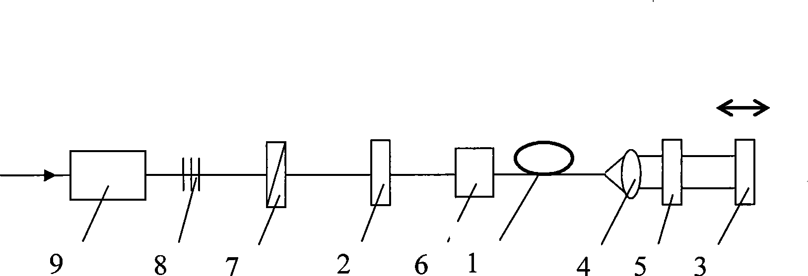
[0101] Such as figure 2 As shown, the optical parametric oscillator includes: a nonlinear photonic crystal fiber 1 with double zero dispersion wavelength, a resonant cavity composed of a high reflection mirror 2 and an output mirror 3, a parametric oscillating light beam collimator 4, and a parametric light width compressor 5 , pump optical coupler 6, λ / 2 phase retarder 7, pump optical power controller 8 and optical isolator 9.

[0102] The high reflection mirror 2 and the output mirror 3 form a resonant cavity, the double zero-dispersion wavelength nonlinear material 1 is placed in the resonant cavity, the parametric oscillating light beam collimator 4 is placed at the output end of the double zero-dispersion wavelength nonlinear material 1, and the parametric The light width compressor 5 is placed in the optical path collimated by the parametric oscillating light beam collimator 4, the pump optical coupler 6 is placed in the resonant cavity close to the high reflection mirr...


PUM

PropertyMeasurementUnit
Wavelengthaaaaaaaaaa
Lengthaaaaaaaaaa
Lengthaaaaaaaaaa

Abstract

The invention relates to an optical parametric oscillator, which comprises a nonlinear optical material (1) with the double-zero dispersion wavelength, a high reflector (2), an output mirror (3), a parametric oscillation optical beam collimator (4), a parametric optical line width compressor (5), a pumped optical coupler (6), a lambda/2 phase retarder (7), a laser power controller (8) and an optical isolator (9). The nonlinear optical material (1) has a double-zero dispersion wavelength and is arranged in a resonant cavity formed by the high reflector and the output mirror. The pumped optical wavelength is in the anomalous dispersion regime of the photonic crystal fiber, thereby ensuring the phase matching conditions and generating the highly efficient four-wave mixing effect. For the parametric oscillation formed by simplifying the four-wave mixing, the wavelengths of the two parametric lights are respectively arranged at the double-zero dispersion wavelength of the photonic crystal optical fiber, thereby realizing the group velocity dispersion compensation of the parametric light, solving the problem of the ultra-short pulse dispersion compensation, and greatly reducing the pumping threshold.

Description

technical field [0001] The invention belongs to the field of optoelectronics and laser technology, and relates to the fields of optical waveguide theory and technology, nonlinear optics, photonics and technology. It is suitable for applications in the fields of military laser, space laser communication, laser medicine, laser nuclear fusion, laser processing, laser spectroscopy and precision optical measurement. Background technique [0002] The optical parametric oscillator is still an effective technology for realizing laser frequency conversion at present. The general optical parametric oscillator uses nonlinear optical crystals, but due to the limitations of phase matching, effective nonlinear coefficient and optical transmission band, it lacks effective nonlinear In optical crystals, optical parametric oscillators cannot be realized in many wavelength ranges. In particular, the lack of high-quality mid-to-far infrared laser crystals and nonlinear crystals severely restr...

Claims


Application Information

Patent Timeline
IPC IPC(8): H01S3/091H01S3/094H01S3/16H01S3/10G02F1/35G02F1/355
Inventor 郑义李春里赵陆萍朱宜存左伟丽王春沈建平刘杰郭颖任怀远
Owner BEIJING JIAOTONG UNIV
Why Eureka
Try Eureka