Solar energy collector with XY or XYZ sun tracking table

a solar energy collector and sun tracking technology, applied in the direction of heat collector mounting/support, machines/engines, light and heating apparatus, etc., can solve the problems of unused space further reducing the overall efficiency of the prior art csp farm, etc., to improve the overall efficiency, reduce the overall efficiency, and save energy

Inactive Publication Date: 2016-03-01
MARTIN LOPEZ FERNANDO RAMON
View PDF8 Cites 2 Cited by
  • Summary
  • Abstract
  • Description
  • Claims
  • Application Information

AI Technical Summary

Benefits of technology

[0001]This invention relates generally to solar energy collectors and, more particularly, to a sun tracking table that improves their operating efficiency.
[0002]Numerous devices for harnessing the sun's energy are described in the prior art. U.S. Pat. Nos. 7,558,452 and 8,165,435 are directed to solar energy collectors that employ domed structures and fiber optics, but neither teaches tracking the sun's position as it changes throughout the day. Some prior art solar energy collectors teach tracking the sun by rotating collector mirrors and adjusting associated angles such as azimuth. Prior art industrial solar collectors that employ photo voltaic (PV) solar cells utilize complex three-dimensional mechanisms to move the entire PV panel in order to track the sun. Concentrated Solar Power (CSP) farms that employ concentrators utilizing mirrors or parabolic lenses occupy large areas of land on the order of a square mile Prior art CSP collectors of the type manufactured by Stirling Energy Systems under the product name SunCatcher that employ mirrors to concentrate the sun's rays require three-dimensional controlled movement of the entire collector array in order to track the sun. These prior art mirror collectors must be very sturdily constructed in order to handle the torsional forces resulting from mounting the heavy Stirling engine at the focal point of the mirror-covered parabolic dish. Considerable energy is wasted by the sun tracking mechanisms utilized to move these bulky prior art dishes over their full range of motion, thus reducing overall operating efficiency. Furthermore, sufficient space must be provided adjacent each collector array to prevent mechanical interference with other arrays within a CSP farm. This unused space further reduces the overall efficiency of the prior art CSP farms.
[0003]It would be advantageous to provide a solar energy collector utilizing one or more Fresnel lenses formed in a chosen geometric shape for focusing solar energy as one or more sun ray spots.
[0004]It would be further advantageous to provide a solar energy collector having a tracking table for tracking the movement of a sun ray spot impinging thereon.
[0005]It would be further advantageous to provide a solar energy collector having a wheel-equipped Stirling engine positioned on a flat or otherwise prepared surface to facilitate easy movement, controlled by a tracking table positioned proximate the flat surface, in concert with a moving sun ray spot impinging on a heat element of the Stirling engine.
[0006]These and other advantages are accomplished in accordance with the illustrated preferred embodiments of the present invention described below that serve to minimize the structural and operating costs associated with prior art solar energy concentrators that have enjoyed widespread commercial use in CSP farms.BRIEF DESCRIPTION OF THE DRAWINGS

Problems solved by technology

Considerable energy is wasted by the sun tracking mechanisms utilized to move these bulky prior art dishes over their full range of motion, thus reducing overall operating efficiency.
This unused space further reduces the overall efficiency of the prior art CSP farms.

Method used


Image

  • Solar energy collector with XY or XYZ sun tracking table
  • Solar energy collector with XY or XYZ sun tracking table
  • Solar energy collector with XY or XYZ sun tracking table

Examples


Embodiment Construction

[0017]It is well understood in the solar energy collection industry that approximately one kilowatt of solar power can be collected on a surface having an area of one square meter. Assuming an operating efficiency of approximately 25%, approximately four kilowatts of power can be collected on a surface having an area of four square meters. That collection area and associated power generation capability are compatible with the requirements of the average homeowner.

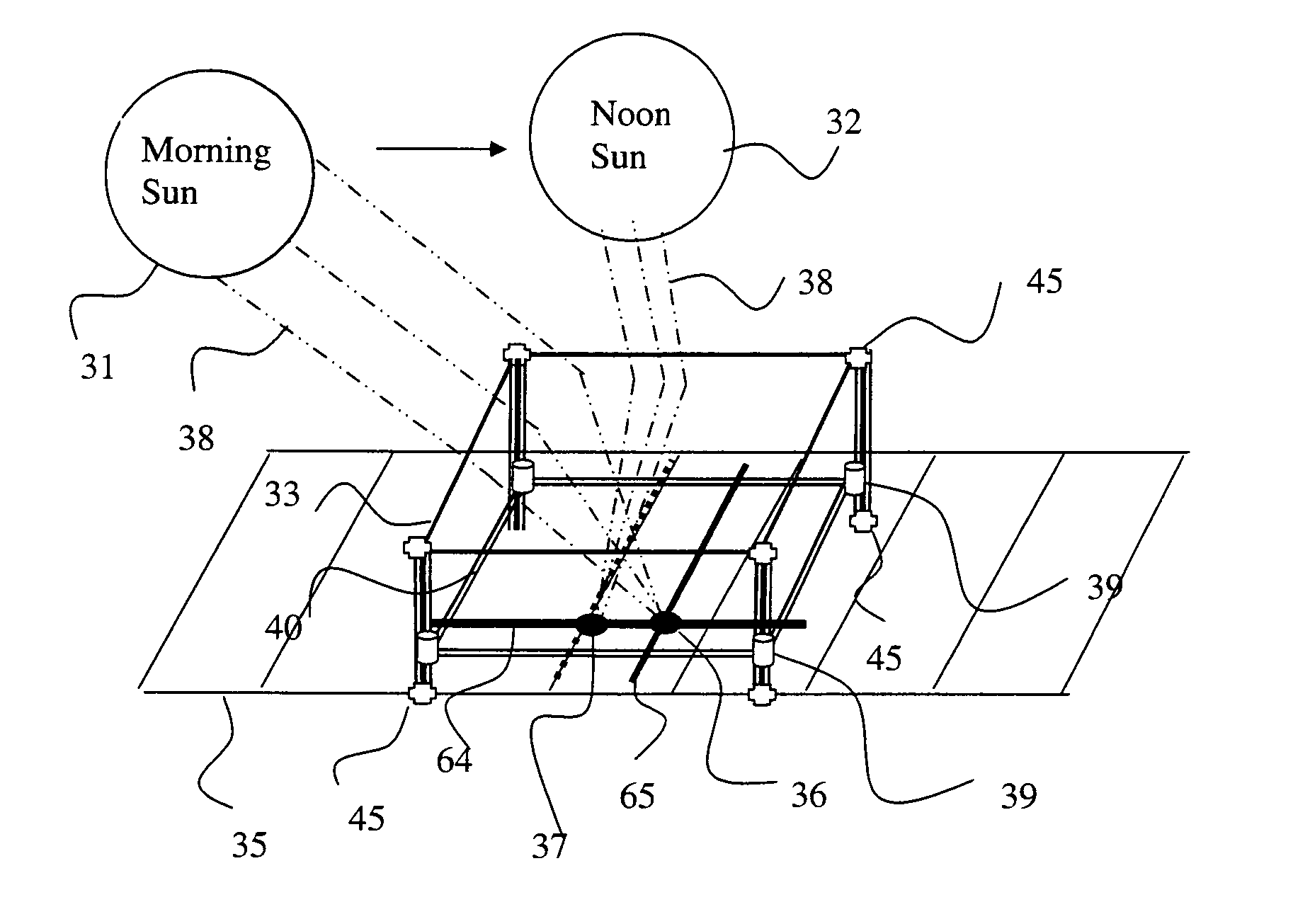
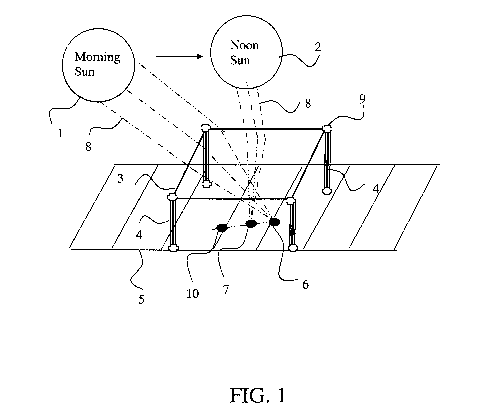
[0018]The solar energy collector of the present invention utilizes Fresnel lenses for concentrating sunlight onto a collection surface. Fundamentally, various shapes and sizes of Fresnel lenses may be utilized. For example, the rectangular Fresnel lens 3, illustrated in FIG. 1, will work well once the sun has risen to position 1 that is approximately 30° above the eastern horizon. When the sun is in morning position 1, lens 3 will focus the sun's rays 8 at a sun ray spot 6 on a flat or otherwise prepared surface 5. A plural...


PUM


Abstract

A solar energy collector utilizes one or more Fresnel lenses supported above a prepared surface for focusing sunlight at one or more sun ray spots. One or more tracking tables sense and track, during the course of the day, the movement of associated ones of the sun ray spots. Curved Fresnel lenses produce sun ray spots focused an offset distance above associated ones of one or more tracking tables, depending upon the sun's position. The sun ray spots may be forced to lie on the one or more tracking tables by moving an associated tracking table upward a distance equal to the offset distance. One or more wheel-equipped Stirling engines are positioned on the prepared surface and are conventionally controlled for tracking movement in concert with an associated sun ray spot.

Description

BACKGROUND AND SUMMARY OF THE INVENTION[0001]This invention relates generally to solar energy collectors and, more particularly, to a sun tracking table that improves their operating efficiency.[0002]Numerous devices for harnessing the sun's energy are described in the prior art. U.S. Pat. Nos. 7,558,452 and 8,165,435 are directed to solar energy collectors that employ domed structures and fiber optics, but neither teaches tracking the sun's position as it changes throughout the day. Some prior art solar energy collectors teach tracking the sun by rotating collector mirrors and adjusting associated angles such as azimuth. Prior art industrial solar collectors that employ photo voltaic (PV) solar cells utilize complex three-dimensional mechanisms to move the entire PV panel in order to track the sun. Concentrated Solar Power (CSP) farms that employ concentrators utilizing mirrors or parabolic lenses occupy large areas of land on the order of a square mile Prior art CSP collectors of ...

Claims


Application Information

Patent Timeline
Patent Type & Authority Patents(United States)
IPC IPC(8): B60K16/00F03G6/06F01B29/10F24J2/38F24J2/40F24J2/08F24S23/30F24S50/20
CPCF24J2/085F24J2/38F24J2/40F03G6/068Y02E10/46F03G6/06Y02E10/47F24S23/31F24S25/10F24S30/20F24S50/20F24S2020/23F24S2080/503F24S50/00
Inventor MARTIN-LOPEZ, FERNANDO, RAMON
Owner MARTIN LOPEZ FERNANDO RAMON
Why Eureka
Try Eureka