
Apparatus and method for manufacturing a light-emitting device using a neutral particle beam

a manufacturing apparatus and light-emitting device technology, applied in the direction of polycrystalline material growth, crystal growth process, chemically reactive gas, etc., can solve the problems of deterioration of the substrate on which nitride semiconductor thin films are made, damage to thin films, and limited application area of single crystals made at such a high temperature. , to achieve the effect of reducing the temperature of the substrate, high efficiency and high quality

Active Publication Date: 2016-03-01
KOREA INST OF FUSION ENERGY
View PDF7 Cites 0 Cited by
  • Summary
  • Abstract
  • Description
  • Claims
  • Application Information

AI Technical Summary

Benefits of technology

[0056]As a result of the present invention, the temperature of the substrate can be lowered considerably since the energy required for the formation of nitride semiconductor single crystal thin films during the manufacture of a light emitting device is determined by the arrangement of the quantum of thermal energy and by the kinetic energy of the neutral particle beam. Therefore, high efficiency and high quality LED devices can be manufactured because, compared to conventional technology, thermal deformation of the substrate itself can be prevented and the problems of diffusion of doping impurities over the boundaries in multilayer thin films of LED, will be resolved.
[0057]In addition, as a result of the present invention, since the nitride semiconductor thin film is formed as a single-crystal from the beginning by the neutral particle beam, a much more convenient method and device is provided, compared to methods and their corresponding manufacturing equipment wherein poly crystal thin film is formed and then single crystallized, so that the price competitiveness of semiconductor light emitting devices can be improved.
[0058]In addition, as a result of the present invention, the problem that the quality of the light-emitting device is degraded due to the diffusion of p-type impurities to other layers is prevented as though the doping efficiency of the p-type semiconductor layer in the light emitting element increases.

Problems solved by technology

The application area of single crystals that are made at such a high temperature is very limited.
To obtain a nitride semiconductor thin film using these methods, the substrate should be maintained at a temperature between 1,050 and 1,100° C. Accordingly, deterioration of the substrate on which nitride semiconductor thin films are formed, for example due to thermal expansion of the sapphire substrates, or deformation of the substrate itself, can be a problem.
Furthermore, the difference in lattice constant and coefficient of thermal expansion between the nitride semiconductor thin film formed on the substrate and the substrate can damage a thin film, which can be a problem.
For example, Mg doping atoms used to form the p-type GaN layer may spread into the multi-quantum well, the active layer of an LED, so that the emission characteristics of the light-emitting device is impaired.
Therefore, the emission characteristics of the light-emitting device will be ultimately degraded.
Also, since reflectors of various structures should be provided in order to investigate the predetermined angle of the neutral particle beam for the purification of the films, a lot of effort must go into the production process and complex production equipment is required, which then increases the production costs of the semiconductor light-emitting devices leading to a lower LED supply or decreased marketability.

Method used


Image

  • Apparatus and method for manufacturing a light-emitting device using a neutral particle beam
  • Apparatus and method for manufacturing a light-emitting device using a neutral particle beam
  • Apparatus and method for manufacturing a light-emitting device using a neutral particle beam

Examples


Embodiment Construction

Technical Challenges

[0011]Therefore, the goal of this invention is to supply a manufacturing method and apparatus for manufacturing a light emitting device using a neutral particle beam that can grow high quality nitride semiconductor single-crystal thin films while maintaining a process temperature much lower than in conventional manufacturing processes. Hereby, in order to solve the aforementioned problems when manufacturing semiconductor light emitting devices, instead of using a high process temperature applied to the substrate, a neutral particle beam of the appropriate energy is instead used.

[0012]Another object of the invention is to simplify the required equipment and reduce the effort to manufacture high quality nitride semiconductor single crystal films in order to improve the price competitiveness of semiconductor light emitting devices.

[0013]Also, the other purpose of this invention is to supply the best manufacturing method and apparatus for producing light-emitting ele...


PUM

PropertyMeasurementUnit
temperatureaaaaaaaaaa

Abstract

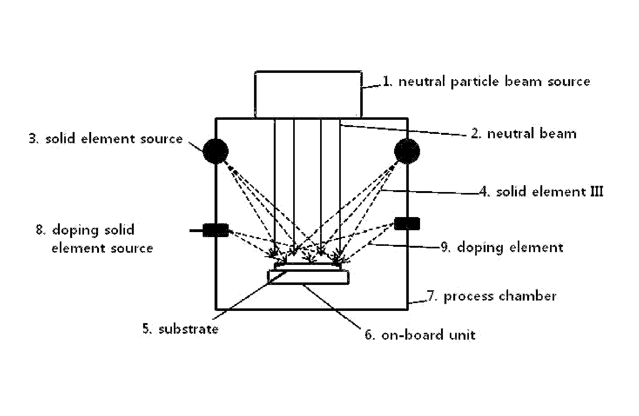
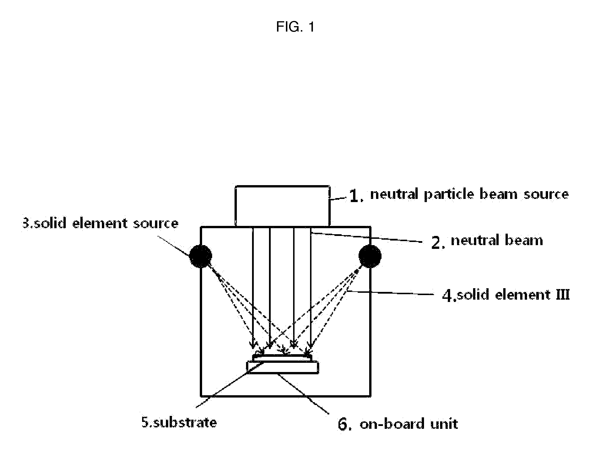
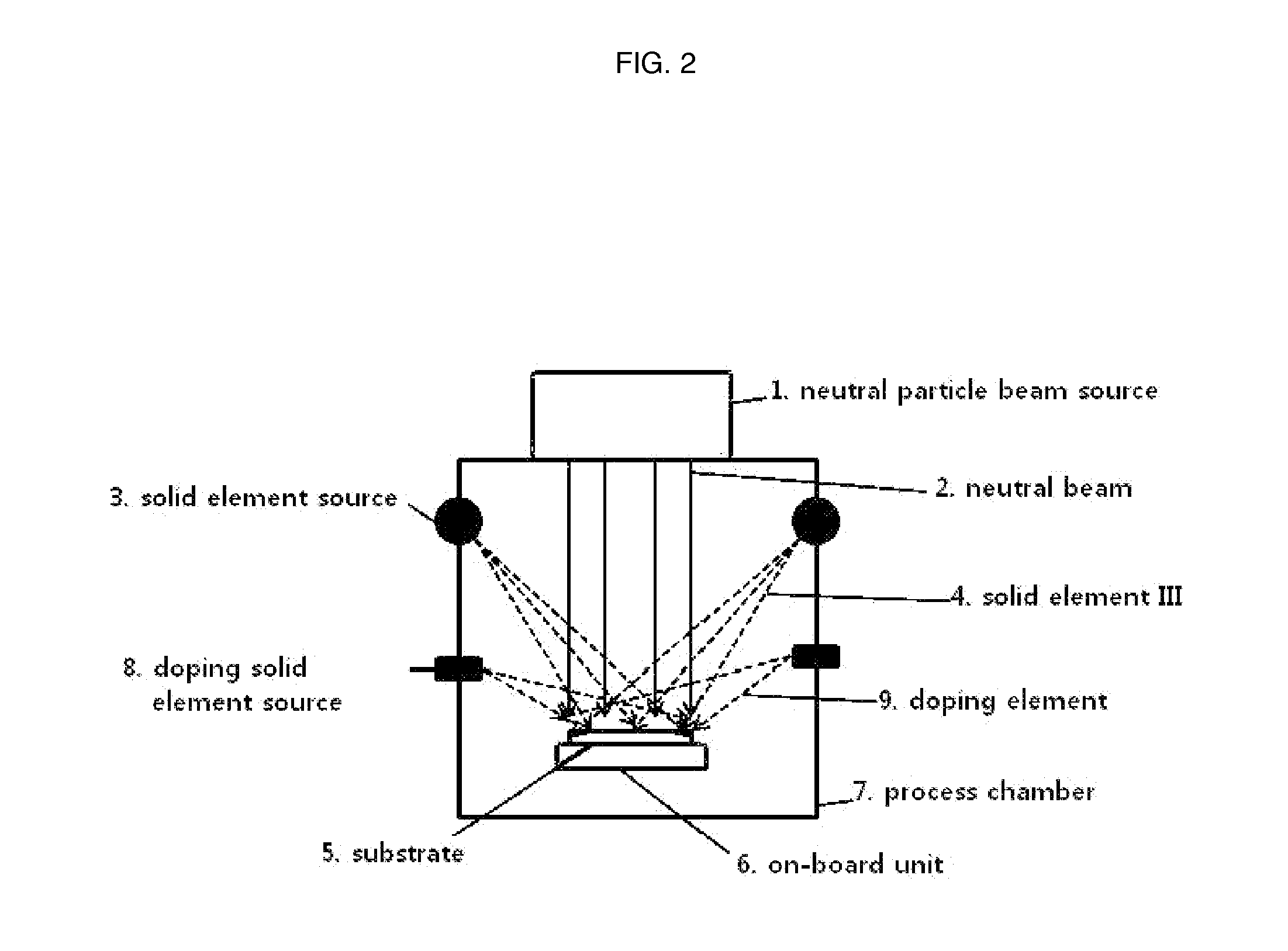
The present invention relates to an apparatus and method for manufacturing a semiconductor light-emitting device using a neutral particle beam. According to the present invention, since the kinetic energy of the neutral particle beam is provided as a portion of the reaction energy for causing a nitride semiconductor single crystal thin film to be formed on a substrate, and the reaction energy is not provided as heat energy by heating a substrate as in the prior art, the substrate may be treated at a relatively low temperature. Furthermore, elements such as Si, Mg, and the like, which are solid elements required for doping are sprayed onto the substrate from a source which generates solid elements for doping together with the neutral particle beam to achieve high doping efficiency at a lower temperature. According to the present invention, since the substrate is treated at a low temperature, the degradation of the substrate and thin film may be prevented, and the undesired diffusion of the doping elements may be prevented to enable the manufacture of the semiconductor light-emitting device having superior light-emitting properties in a relatively easy manner.

Description

TECHNOLOGY FIELD[0001]The present invention relates to a manufacturing method and manufacturing apparatus for a light emitting device. In more detail, it relates to the use of a neutral particle beam method and system for single crystal nitride semiconductor formation in which thin film deposition occurs at a low temperature.BACKGROUND OF THE INVENTION[0002]In general, nitride single crystal semiconductor thin film deposition is widely used[0003]for forming a light-emitting diodes (LED) or a laser diodes. In order to form nitride single crystal semiconductors on a substrate it is generally necessary to maintain the substrate at a high temperature.[0004]Conventional thin film processes require temperatures above 1,000° C. for crystal growth. The application area of single crystals that are made at such a high temperature is very limited.[0005]Typical technologies used to form conventional nitride semiconductor crystals include MOCVD (Metal Organic CVD) and MBE (Molecular Beam Epitaxy...

Claims


Application Information

Patent Timeline
Patent Type & Authority Patents(United States)
IPC IPC(8): H01L21/02C30B29/40C30B25/10C30B25/02H01L33/00H01L21/67
CPCH01L21/0257C30B25/02C30B25/105C30B29/406H01L21/0254H01L21/0262H01L21/02458H01L21/02576H01L21/02579H01L21/02631H01L21/02656H01L21/67161H01L21/67207H01L33/0066H01L33/32
Inventor YOO, SUK, JAEKIM, SEONG, BONG
Owner KOREA INST OF FUSION ENERGY
Learn More