Tilt steering system

a technology of tilt steering and abutment portion, which is applied in the direction of steering parts, vehicle components, transportation and packaging, etc., can solve the problems of reducing affecting the efficiency of assembly work, and unable to adopt means in many cases excluding cases where extra space is available, so as to reduce the occurrence reduce production costs, and eliminate the effect of large difference in operation for

Active Publication Date: 2016-03-15
NSK LTD
View PDF28 Cites 3 Cited by
  • Summary
  • Abstract
  • Description
  • Claims
  • Application Information

AI Technical Summary

Benefits of technology

[0044]According to the invention described heretofore, it is possible to realize the tilt steering system which eliminates the occurrence of a large difference in operation force necessary to operate the adjustment lever whether the steering wheel is situated in the upper or lower position.
[0045]Namely, in the pair of supporting plate portions which hold the displacement bracket fixed to the steering column therebetween, the sum of the thicknesses of the portions which are held by the anchor portion and the presser member is smaller on the mounting plate portion side where the rigidity of the supporting plate portions is high than on the non-mounting plate portion side where the rigidity of the supporting plate portions is low. Additionally, a reaction force produced in association with contracting the space between the anchor portion and the presser member by rotating the adjustment lever tends to be smaller on the mounting plate portion side by such an extent that the sum of the thicknesses is so small. In addition, this reaction tends to be larger on the side where the rigidity is high than on the side where the rigidity is low, and therefore, these tendencies are offset by each other so that the reaction force is allowed to remain almost constant. The operation force required to rotate the adjustment lever is almost in proportion to the reaction force, and therefore, the operation force is allowed to remain almost constant by causing the reaction force to remain almost constant, thereby making it possible to mitigate or eliminate the sensation of physical disorder felt by the driver who operates the adjustment lever.
[0046]In addition, the reaction force changes largely as a result of a slight change in the sum of the thicknesses. Consequently, the thickness of the unequal-thickness supporting plate portion only has to be changed slightly along the vertically elongated hole, and the thickness of the peripheral portion of the vertically elongated hole can be changed to a desired value easily at the same time that the unequal-thickness supporting plate portion is bent or punched through pressing. Additionally, there is imposed no limitation on the assembling direction of both the anchor portion and the presser portion. Consequently, the production costs are never increased. In addition, the operation force necessary to operate the adjustment lever can be adjusted finely by changing the degree at which the thickness of the peripheral portion changes, and therefore, the difference in operation force of the adjustment lever associated with the difference in vertical position of the steering wheel can be eliminated sufficiently. Further, the inner surfaces of the anchor portion and the presser portion are in abutment with the outer surfaces of the supporting plate portions over the sufficient area. Consequently, the areas of the abutment portions between the inner surfaces of the anchor portion and the presser member and the outer surfaces of the supporting plate portions are not increased excessively, whereby the steering wheel can smoothly be adjusted with respect to its vertical position by suppressing the plastic deformation of the inner surfaces and the outer surfaces.

Problems solved by technology

In contrast to this, as described in, for example, Patent Document 4, in a construction in which a displacement bracket is provided on an upper side of a steering column, when a steering wheel is positioned at an upper end of an adjustment range thereof, it becomes difficult to ensure a surface contact pressure at abutment portions between inner surfaces of supporting plate portions and outer surfaces of the displacement bracket.
However, this means cannot be adopted in many cases excluding a case where extra space is available for placement of a steering system since a position where the steering column 6a is placed is situated on a lower side as long as a height position of a portion provided on the side of a vehicle body where the supporting bracket 14a is assembled remains the same.
However, in the case of the former construction, since a direction in which the anchor portion and the driven-side cam are assembled is limited (they cannot be assembled in a vertically reverse direction), the efficiency of assembling work is reduced.
In addition, in the case of the latter construction, not only is an extra step of depressing the outer surfaces of the supporting plate portions through surface pressing necessary but also a step is necessary of removing burrs which are produced in association with the surface pressing, resulting in an increased production cost.
Additionally, in either of the constructions, it is not possible to make a fine adjustment of a force necessary to operate the adjustment lever, and hence, the difference in operation force to operate the adjustment lever which is caused in association with the difference in vertical position of the steering wheel cannot necessarily be eliminated sufficiently.
Then, when they are plastically deformed, it is not possible to effect a smooth adjustment of the vertical position of the steering wheel.

Method used


Image

  • Tilt steering system
  • Tilt steering system
  • Tilt steering system

Examples


Embodiment Construction

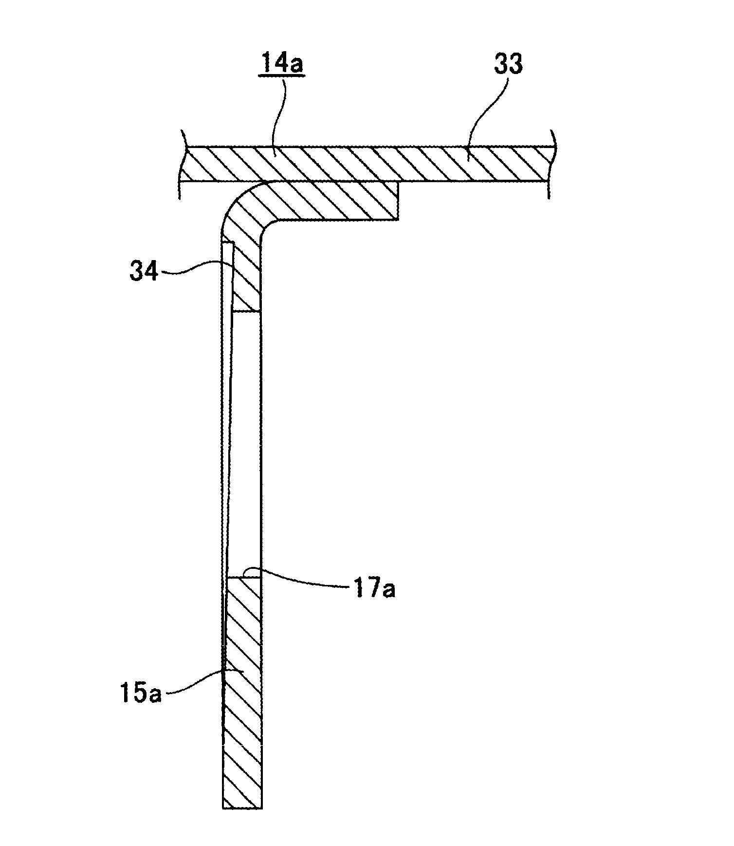
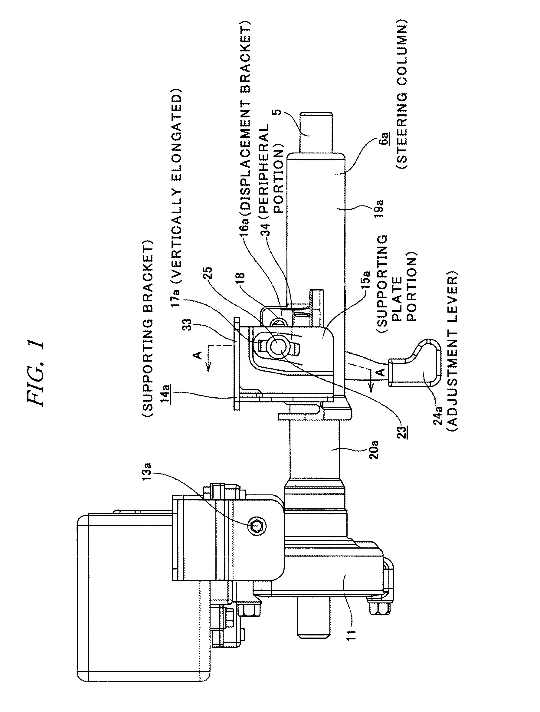
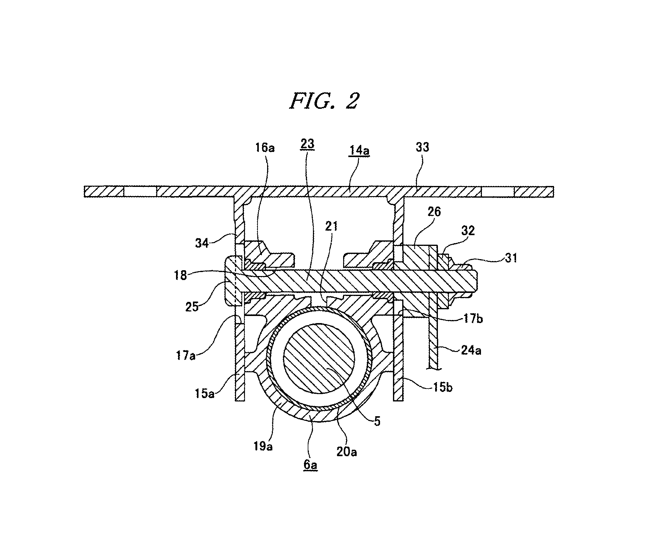
[0056]FIGS. 1 to 4 show an embodiment of the invention. A construction of this embodiment includes a telescopic mechanism which adjusts a longitudinal position of a steering wheel 1 (refer to FIG. 1) as well as a tilt mechanism which adjust a vertical position thereof. In order to include the telescopic mechanism, a steering column 6a is used in which a rear portion of an inner column 20a is fitted in a front portion of the outer column 19a so that the overall length thereof can be extended and contracted. Additionally, a displacement bracket 16a is fixed to an upper side of the front portion of the outer column 19a, and through holes 18 which are elongated in an axial direction of the outer column 19a are formed in this displacement bracket 16a. In addition, a slit 21 along the axial direction of the outer column 19a is formed in a widthwise central portion on an upper surface of a front portion of the displacement bracket 16a, so that a bore diameter of the front portion of the ou...


PUM


Abstract

A construction is realized in which a large difference in operation force to operate an adjustment lever 24a never occurs irrespective of a vertical position of a steering wheel and which is produced at low costs.In part of a supporting plate portion 15a of a pair of left and right supporting plate portions 15a which make up a supporting bracket 14a, a thickness of a peripheral portion 34 which surrounds a vertically elongated hole 17a is made small at an upper portion and large at a lower portion. Additionally, a change in operation force of the adjustment lever 24a based on the difference in thickness and a change in the operation force based on a difference in rigidity of the supporting plate portion 15a are offset by each other to thereby solve the problem.

Description

TECHNICAL FIELD[0001]The present invention relates to an improved tilt steering system for adjusting the height position of a steering wheel according to the build and driving posture of a driver. Specifically, the invention is intended to realize a construction which can provide a large magnitude of force which is sufficient to hold the height position of the steering wheel in the adjusted position without particularly increasing an operation force to operate an operation lever. It is noted that the tilt steering system which is a target of this invention includes not only the construction in which only the height position of the steering wheel can be adjusted but also a so-called tilt and telescopic steering system in which a back-and-force position as well as a height position of a steering wheel can be adjusted.BACKGROUND ART[0002]A motor vehicle steering system is configured as shown in FIG. 7 so that a rotation of a steering wheel 1 is transmitted to an input shaft 3 of a stee...

Claims


Application Information

Patent Timeline
Patent Type & Authority Patents(United States)
IPC IPC(8): B62D1/184B62D1/189
CPCB62D1/184B62D1/189
Inventor KII, HIROYUKI
Owner NSK LTD
Why Eureka
Try Eureka