Measurement device for pile displacement and method for use of the same

a measurement device and pile technology, applied in the direction of measurement devices, electric/magnetic measuring arrangements, instruments, etc., can solve the problems of difficult to accurately measure, difficult to measure based on a marker, and inability to have the accuracy needed for the “end of drive” portion of the driving process, etc., to achieve accurate detection of phase changes and low cost

Active Publication Date: 2016-03-15
PILE DYNAMICS
View PDF107 Cites 4 Cited by
  • Summary
  • Abstract
  • Description
  • Claims
  • Application Information

AI Technical Summary

Benefits of technology

This patent describes a system for measuring displacement during the driving process, which involves using a pair of spaced receivers and a single transmitter positioned relative to a structural pile. The system can accurately detect phase changes to measure displacement. This technology can be used alone or in combination with other methods to better determine the depth of the driven pile. Additional transmitters and receivers can be added to increase the range and accuracy of the system, and they can operate on different frequencies without interference.

Problems solved by technology

Many of these systems have been found to be very effective in the field, but some fail to have the accuracy needed for the “end of drive” portion of the driving process.
While this is a low cost and effective way to determine the general depth of the pile, the general depth does not determine whether or not the pile has engaged the underlying bedrock and thus the pile has reached its desired set point.
While incremental displacement can be effective to determine the set point, it is difficult to accurately measure for several reasons including, but not limited to, the violent nature of a pile driving hammer blow.
For example, this is difficult to measure based on a marker positioned on the ground since the ground moves when the pile is struck by the hammer.
However, while Likins has been found to be a very effective system in the field, applicant has found that the depth measurement device of Likins has its limitations which for years went unresolved.
While the linear bearing arrangement is effective in handling the lateral movement of the wire, it is not effective in handling the changes in load in the direction of line 56 wherein it has been found that the support rod, that is used to support the linear bearing, often deforms or fails in use.
In either case, this condition adversely affects the accuracy of the depth sensor and the failure of the system in the field can cause downtime for the pile installation process.
Yet another problem found with the depth measurement system disclosed in the prior art is that the data produced by the system can be corrupted if the line is allowed to go slack.
A slack condition in this line affects this constant and can produce error.
Moreover, if this slack condition is not noticed, the error in the data may not be known, which would result in a less accurate data set for the pile installation period.
Depending on the frequency of the slack condition, and the other factors discussed above, the resulting data could be corrupted enough to prevent its use in evaluating the structural integrity of the installed pile.
Again, accuracy levels of this type of system are well suited for general depth measurements, but can be less than ideal for the end of drive measurement of the driving process.
Yet even further, the wire measurement system tends to lose accuracy as depth increases in that the stretching of the wire increases.
Therefore, a wire measurement system is at its least accurate point during the end of drive.
In that it is difficult to accurately measure the exact pile displacement per blow with many of the systems known in the art, these measurements are often calculated by hand.
However, and as can be appreciated, this system can vary widely based on the expertise of the operators and is not always a repeatable measure of displacement.
Further, while these methods appear simple, they are costly both in the manpower needed to make the measurement and the safety factors that are must be built into these kinds of measurement to ensure that the set point has been reached.
Yet even further, it is difficult, costly and / or impossible to quickly digitize this type of data for remote monitoring and / or data storage.
Attempts have been made to address the accuracies relating to depth measurement and the needed accuracy during the end of drive of the pile, but these have been found to have their own set of problems.
However, laser systems have had problems in field since they can only be utilized during clear weather.
As can be appreciated, lasers require clear conditions and can be affected by rain and fog.

Method used


Image

  • Measurement device for pile displacement and method for use of the same
  • Measurement device for pile displacement and method for use of the same
  • Measurement device for pile displacement and method for use of the same

Examples


Embodiment Construction

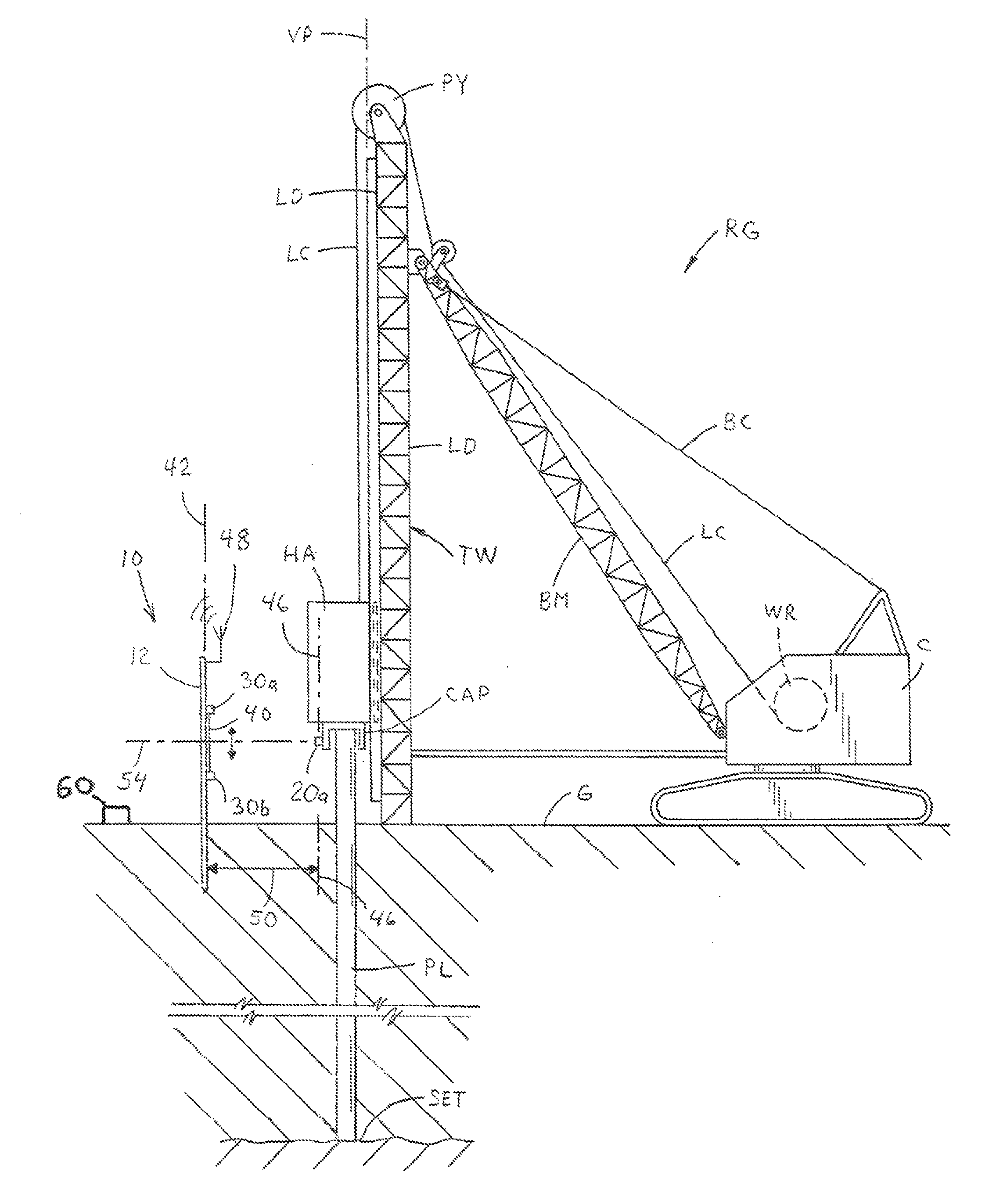
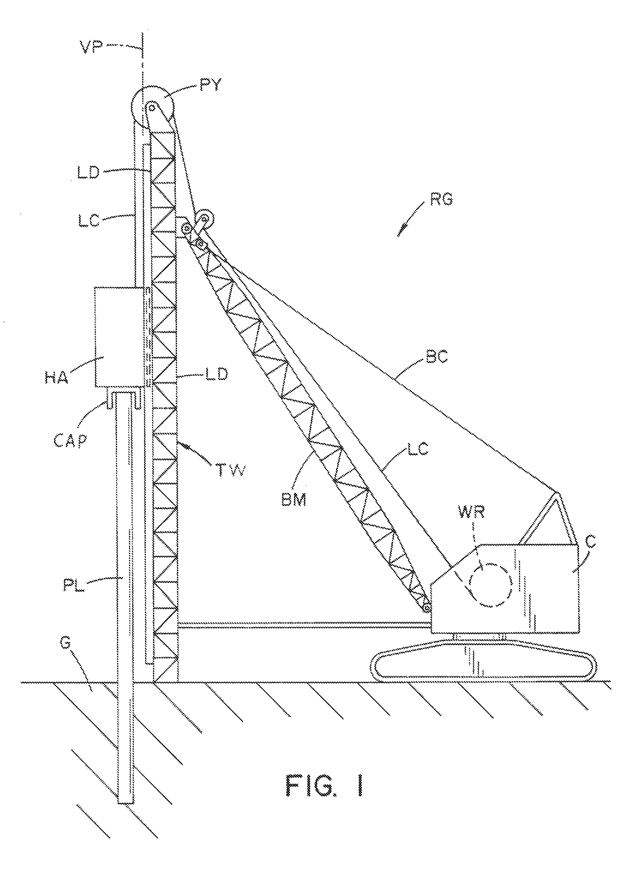
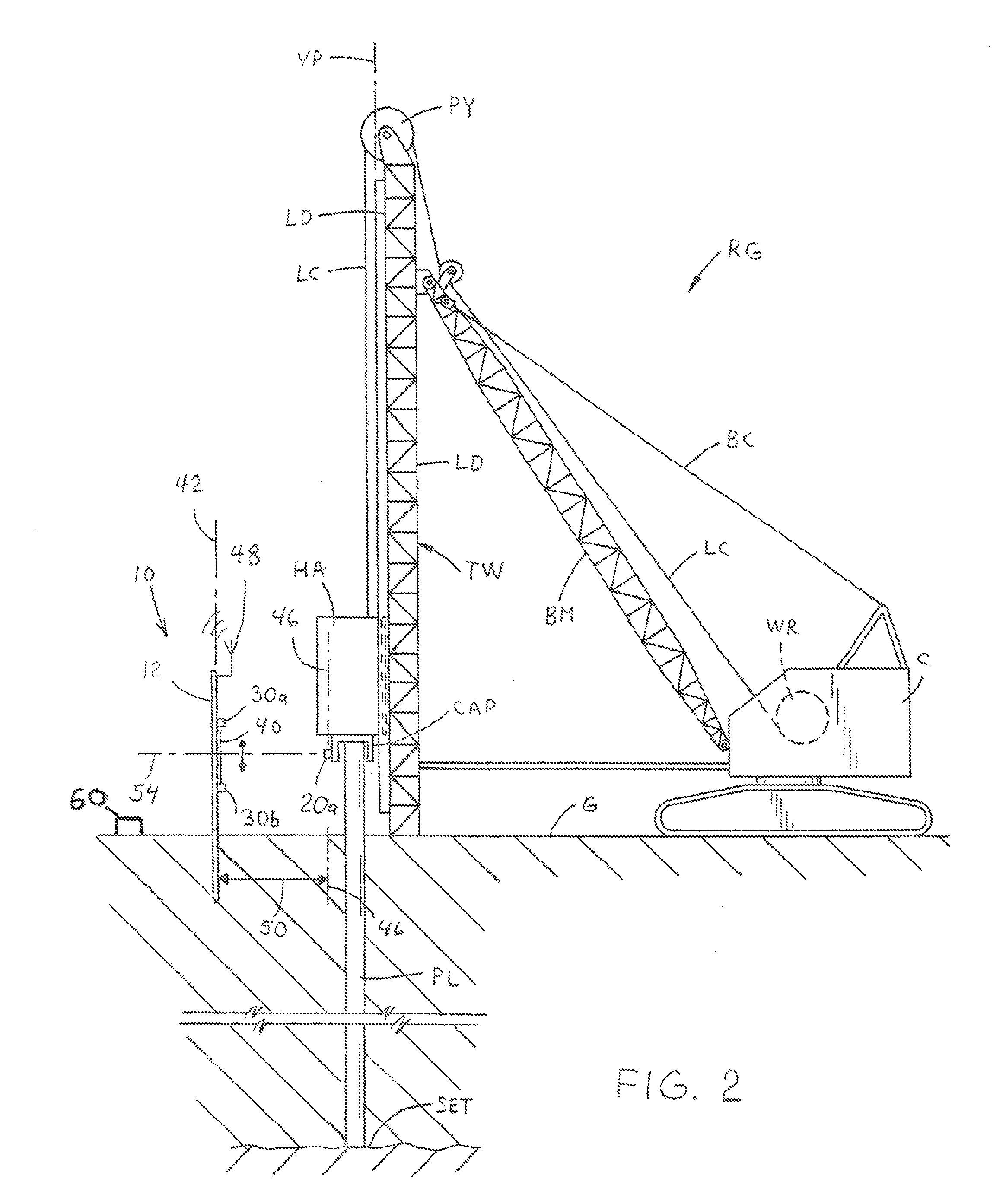
[0037]Referring now to the drawings wherein the showings are for the purpose of illustrating preferred and alternative embodiments of the invention only and not for the purpose of limiting same, FIGS. 1-3A show several views of a rig or pile installation machine RG including measuring devices according to several embodiment of this applications. However, while the invention of this application is being shown in connection with a hammer rig, the invention of this application can be used in connection with other machines including an auger cast pile installation machine.

[0038]Again, Rig RG is intended to be illustrative only and is not intended to limit the invention of this application to a particular rig, or a particular style or type of rig. Conversely, it is intended to be only illustrative of a rig in general. For the rig shown, rig RG is for driving piles and includes a hammer assembly or load box HA that moves relative to tower TW in a vertical plane to hammer a pile PL into a ...


PUM


Abstract

A displacement measuring system to measure the displacement of a structural object that includes a transmitter having a signal generator and an antenna wherein the antenna is securable relative to one of a displaced object and a support. The antenna defines a transmitter axis that is parallel to the displacement axis of the object and a centerline that is perpendicular to the displacement axis. The system further includes a first receiver and a second receiver having antennas securable relative to the other of the object and the support. The receiver antennas are positioned along a receiver axis that is parallel to the displacement axis and being spaced along the receiver axis on either side of the center line. The receiver antennas are configured to detect a signal emitted by the transmitter. The system further includes a phase detector to triangulate phase change and calculate object displacement.

Description

[0001]This application claims priority in Provisional Patent Application Ser. No. 61 / 595,765 filed on Feb. 7, 2012, which is incorporated by reference herein.[0002]The invention of this application relates to devices used to measure the vertical displacement of a driven pile during installation. More particularly, to a highly accurate measurement device for vertical displacement measurement that has been found to work particularly well for use with the “end of drive” measurement portion of the pile driving process.[0003]However, while it has been found to work particular well for this end of drive measurements, the invention of this applicant could be use for detecting all pile displacement.INCORPORATION BY REFERENCE[0004]The following patents and publications are incorporate by reference into the disclosure and specification of this application as background material:[0005]The Johnske U.S. Pat. No. 2,279,466 discloses a radio direction finder; Greene U.S. Pat. No. 2,368,921 disclos...

Claims


Application Information

Patent Timeline
IPC IPC(8): G01B7/14
CPCG01B7/14G01B7/003G01S5/02G01S2205/01
Inventor BERRIS, JR., RICHARD, E.
Owner PILE DYNAMICS
Why Eureka
Try Eureka