Electro-optical apparatus and driving method thereof

a technology of optical apparatus and driving method, applied in the direction of optics, instruments, static indicating devices, etc., can solve the problems of inability to switch between multiple transmittances, inconvenient control or supply of power, slow switching speed, etc., and achieve the effect of superior performan

Active Publication Date: 2016-03-15
YUANHAN MATERIALS INC
View PDF22 Cites 40 Cited by
  • Summary
  • Abstract
  • Description
  • Claims
  • Application Information

AI Technical Summary

Benefits of technology

[0006]The present invention provides a plurality of electro-optical apparatuses with superior performance.
[0007]The present invention provides a plurality of driving method of electro-optical apparatuses, which can cause the electro-optical apparatuses rapidly and accurately switch to the assigned mode.
[0039]In light of above, by utilizing patterned designed electrodes (i.e., the first electrode and the second electrode), the electro-optical apparatus in an embodiment of the present invention can have multiple transmittances and superior performance. By utilizing the driving method of an electro-optical apparatus in an embodiment of the present invention, the electro-optical apparatus can rapidly and accurately switch to a shielding mode or a transparent mode and have superior performance. Besides, the wireless control unit of the electro-optical apparatus in another embodiment of the present invention can supply power to the electro-optical device with convenience, which eliminates the trouble of changing the battery of the electro-optical apparatus. The touch unit of the electro-optical apparatus in yet another embodiment of the present invention can easily control the transmittance of the electro-optical device and further improve the satisfaction while using.

Problems solved by technology

However, there are performance problems such as slow switching speed and unable to switch between multiple transmittances and inconvenient to control or supply power when the conventional electrophoretic apparatuses are utilized as privacy windows.

Method used


Image

  • Electro-optical apparatus and driving method thereof
  • Electro-optical apparatus and driving method thereof
  • Electro-optical apparatus and driving method thereof

Examples


Embodiment Construction

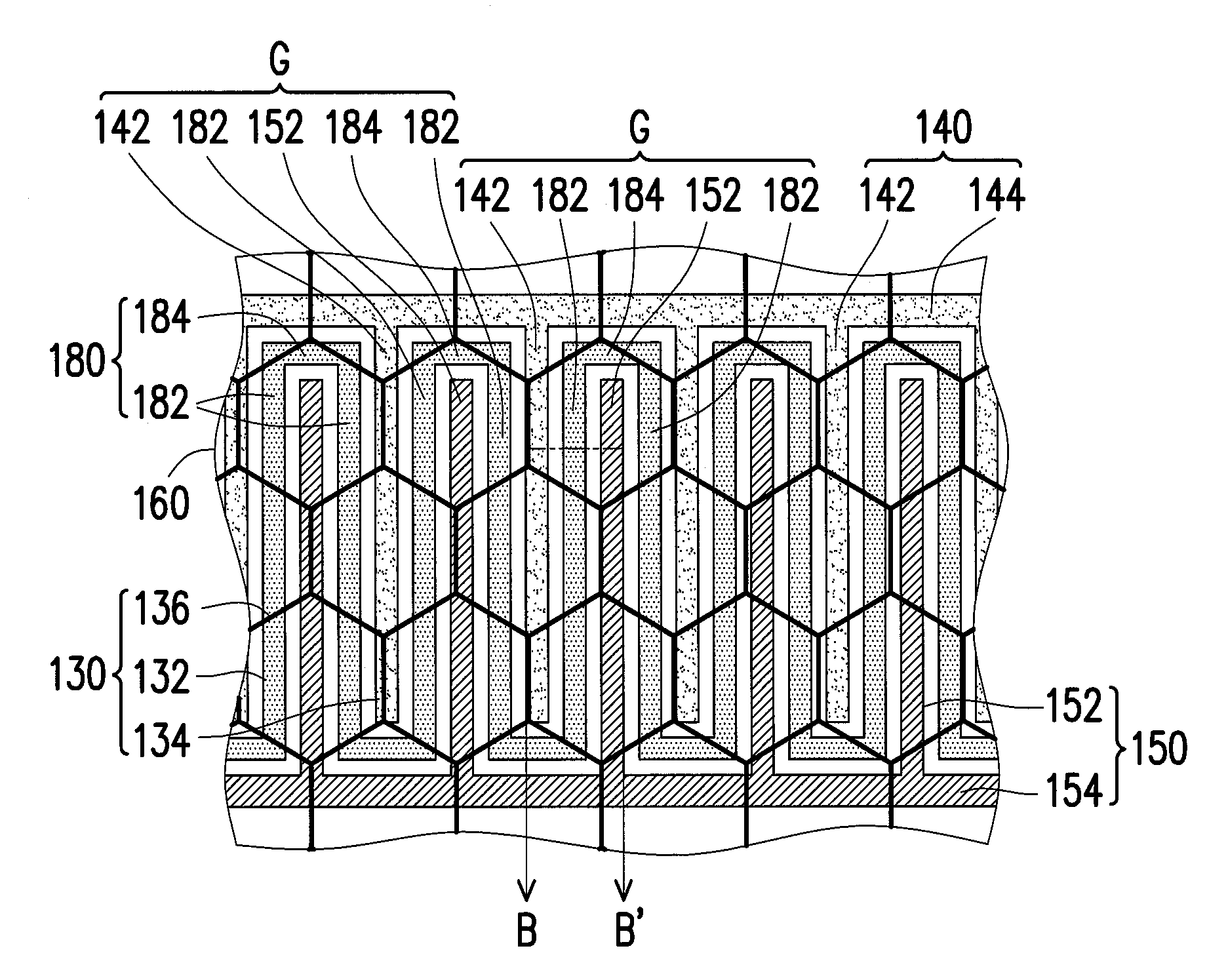
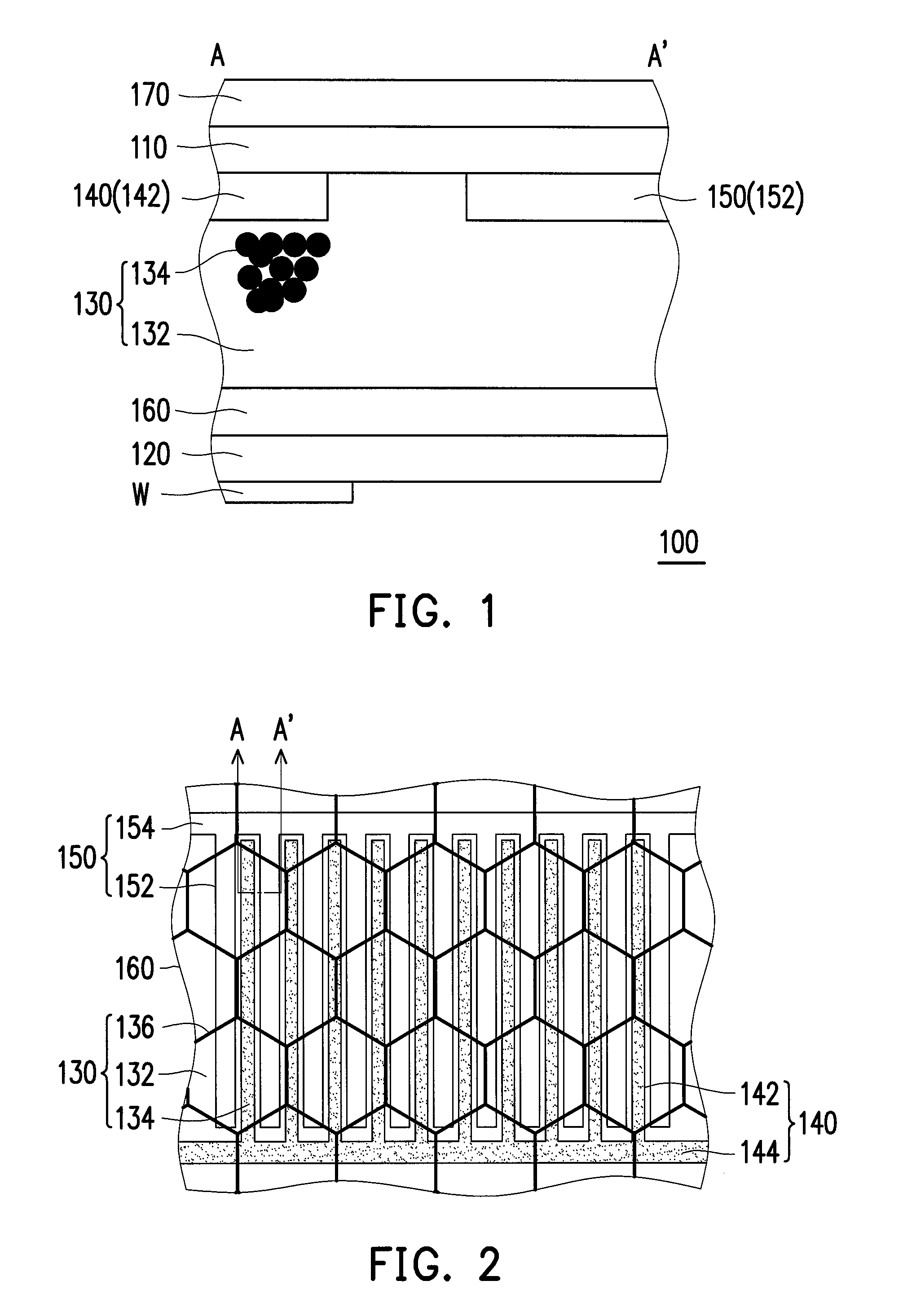
[0053]FIG. 1 is a cross-sectional view of an electro-optical apparatus according to one embodiment of the invention. FIG. 2 is a top view of a first electrode, a second electrode, a third electrode and a display medium layer of an electro-optical apparatus according to an embodiment of the invention. FIG. 1 is particularly corresponded to the line A-A′ inFIG. 2. Please refer to FIG. 1 and FIG. 2, the electro-optical apparatus 100 of the embodiment of the invention includes a first substrate 110, a second substrate 120 disposed opposite to the first substrate 110, a display medium layer 130 disposed between the first substrate 110 and the second substrate 120, a first electrode 140 disposed between the first substrate 110 and the display medium layer 130, a second electrode 150 disposed between first substrate 110 and display medium layer 130 and separated from the first electrode 140, a third electrode 160 disposed between the display medium layer 130 and the second substrate 120. I...


PUM

PropertyMeasurementUnit
driving voltageaaaaaaaaaa

Abstract

An electro-optical apparatus including a first substrate, a second substrate disposed opposite to the first substrate, a display medium layer disposed between the first substrate and the second substrate, a first electrode disposed between the first substrate and the display medium layer, a second electrode disposed between the first substrate and the display medium layer and separated from the first electrode and a third electrode disposed between the display medium layer and the second substrate is provided. The display medium layer includes electrophoretic fluid and charged particles mixed into the electrophoretic fluid. Moreover, driving methods used to drive the electro-optical apparatus and another electro-optical apparatus are also provided.

Description

CROSS-REFERENCE TO RELATED APPLICATION[0001]This application claims the priority benefit of Taiwan application serial no. 102136564, filed on Oct. 9, 2013. The entirety of the above-mentioned patent application is hereby incorporated by reference herein and made a part of this specification.BACKGROUND OF THE INVENTION[0002]1. Field of the Invention[0003]The present invention relates to an electronic apparatus and driving method thereof. More particularly, the present invention relates to an electro-optical apparatus and a driving method thereof.[0004]2. Description of Related Art[0005]Recently, due to the continuous improvement of electro-optical technique, products such as electrophoretic electro-optical apparatuses, liquid crystal electro-optical apparatuses, plasma electro-optical apparatuses, organic light emitting diode electro-optical apparatuses are gradually commercialized and utilized in different sorts of occasions. For example, electrophoretic electro-optical apparatuses ...

Claims


Application Information

Patent Timeline
Patent Type & Authority Patents(United States)
IPC IPC(8): G02B26/00G02F1/167G02F1/1333G02F1/133G02F1/16762G02F1/1685
CPCG02F1/167G02F1/13338G02F2001/13324G02F2001/1672G02F2001/1676G09G3/344G02F1/1676G02F1/1681G02F1/16762G02F1/1685G02F1/13324
Inventor LIU, NIEN-ENFANG, KUO-LUNGHSIEH, YAO-JEN
Owner YUANHAN MATERIALS INC
Why Eureka
Try Eureka