

Ultrasonic decontamination device
a decontamination device and ultrasonic technology, applied in the direction of atomized substances, disinfection, chemicals, etc., can solve the problems of large burden on operators, secondary contamination, and difficulty in keeping the device from contamination in everyday use, and achieve stable decontamination level, effective sterilization, and wide antibacterial spectrum
- Summary
- Abstract
- Description
- Claims
- Application Information
AI Technical Summary
Benefits of technology
Problems solved by technology
Method used
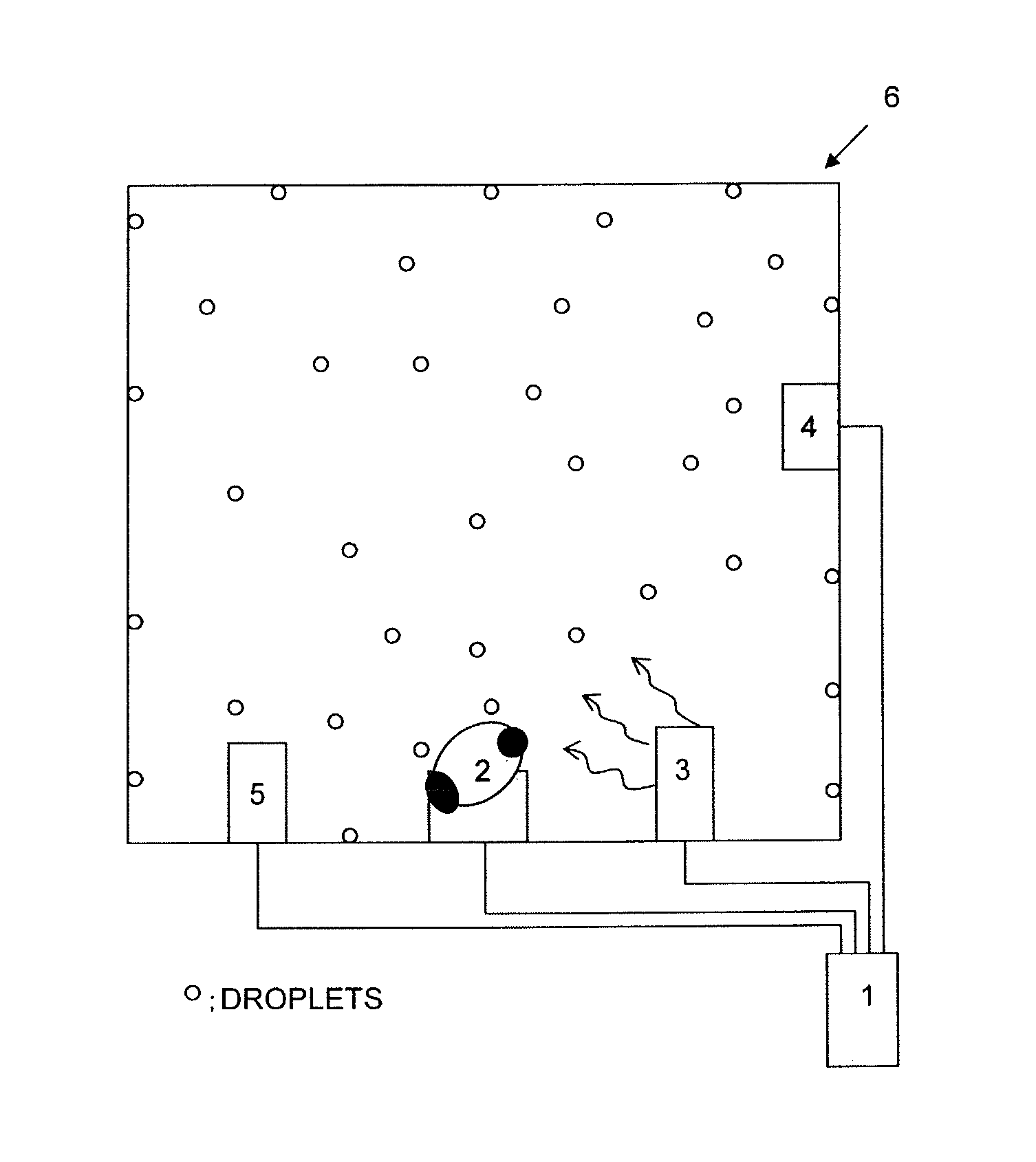
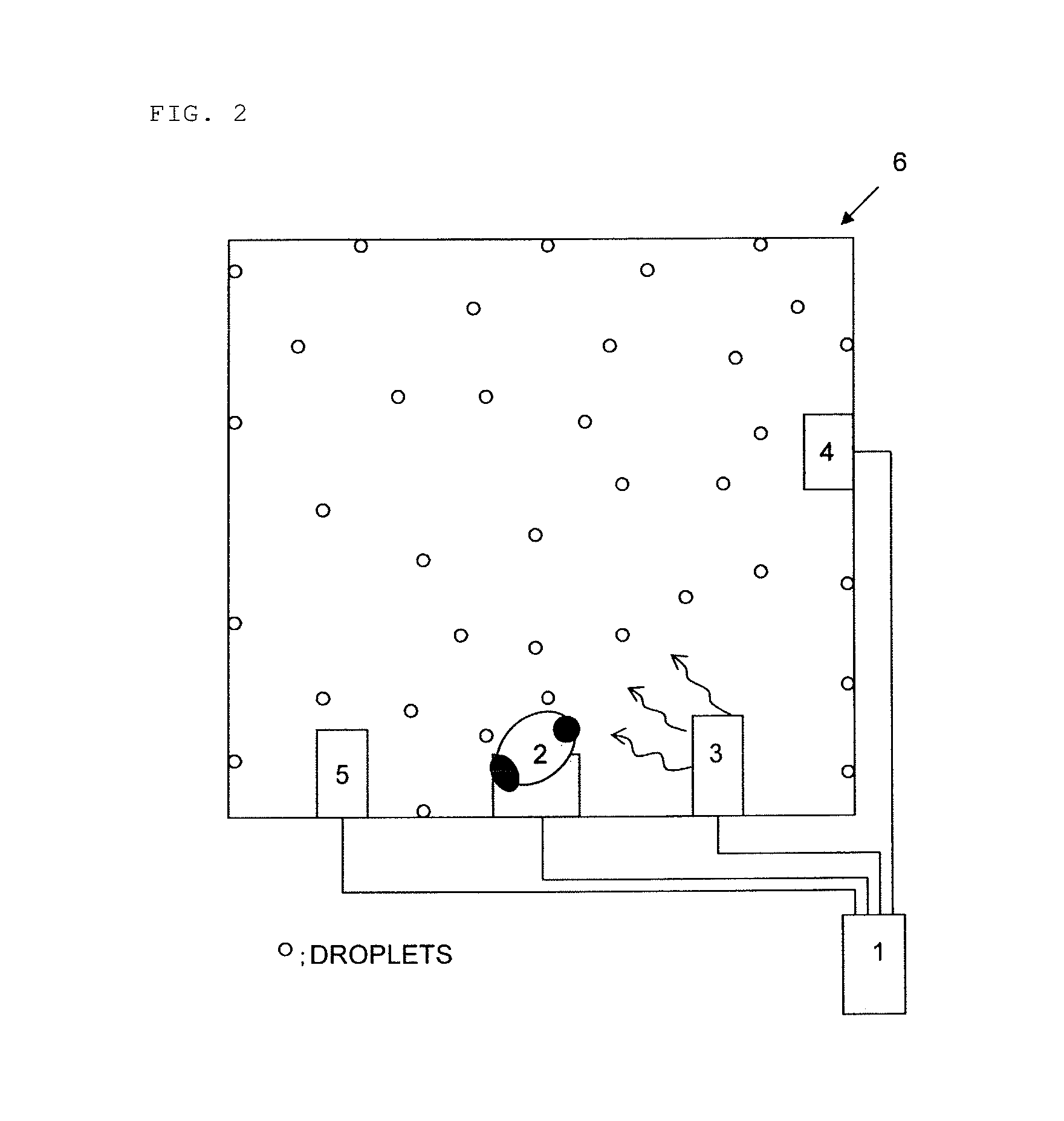
Image


Examples
example 1
[0081]G. stearothermophilus (ATCC #7953), which is a spore-forming bacterium (the number of which is 106), was used as BI. A sterilization period was automatically calculated by using the automatic calculation function, and operation of killing the 106 spore-forming bacteria in a variety of temperature and initial humidity environments was checked. The following table shows results of the checking.
[0082]
TABLE 1High humidityTemperatureNormal humidity(80% PH)15° C.80%, 273 minutes273 minutesnegative (−)negative (−)25° C.39%, 84 minutes162 minutesnegative (−)negative (−)35° C.23%, 61 minutes124 minutesnegative (−)negative (−)45° C.10%, 49 minutes103 minutesnegative (−)negative (−)
example 2
[0083]The decontamination device of the invention (ACTRIL was used as peracetic acid disinfectant) was used to perform sterility tests on a CO2 incubator (manufactured by Ikemoto Scientific Technology Co., Ltd., model 10-0211) and a safety cabinet (manufactured by Sanyo Electric Co., Ltd., model MHW-132AJ). As a biological indicator (BI), Aspergillus brasilus Niger (NBRC 9455), which is prepared fungus spores (the number of which is 106), and G. stearothermophilus (ATCC #7953), which is a spore-forming bacterium (the number of which is 106), were used. Further, a sterilization period (humidity maintained period) was automatically calculated by using the automatic decontamination-period-calculating function. The following tables show results of the tests.
[0084]
TABLE 2Result of test on CO2 incubatorB placement location and incubation resultIntermediateBIUpper levellevelLower levelFungi 106Negative (−)Negative (−)Negative (−)Bacteria 106Negative (−)Negative (−)Negative (−)Set humidity:...
example 3
Effect of Catalyst Fan
[0087]In the decontamination device of the invention, to check an effect of the catalyst fan, the concentration of the hydrogen peroxide was measured in the following cases: (1) the catalyst fan is not used after the sterilization; and (2) the catalyst fan is used after the sterilization. FIG. 5 shows results of the measurement.
[0088]As apparent from FIG. 5, use of the catalyst fan allows the concentration of residual hydrogen peroxide after the sterilization to be quickly lowered.
PUM
| Property | Measurement | Unit |
|---|---|---|
| thickness | aaaaa | aaaaa |
| frequency | aaaaa | aaaaa |
| median diameter | aaaaa | aaaaa |
Abstract
Description
Claims
Application Information