
Continuous preparation of calcined chemically-treated solid oxides

a chemically treated solid oxide and continuous preparation technology, applied in the direction of aluminium oxide/hydroxide, metal/metal-oxide/metal-hydroxide catalyst, fluidised-bed furnace, etc., can solve the problem of long time period of the process

Active Publication Date: 2016-03-22
CHEVRON PHILLIPS CHEMICAL CO LP
View PDF75 Cites 3 Cited by
  • Summary
  • Abstract
  • Description
  • Claims
  • Application Information

AI Technical Summary

Benefits of technology

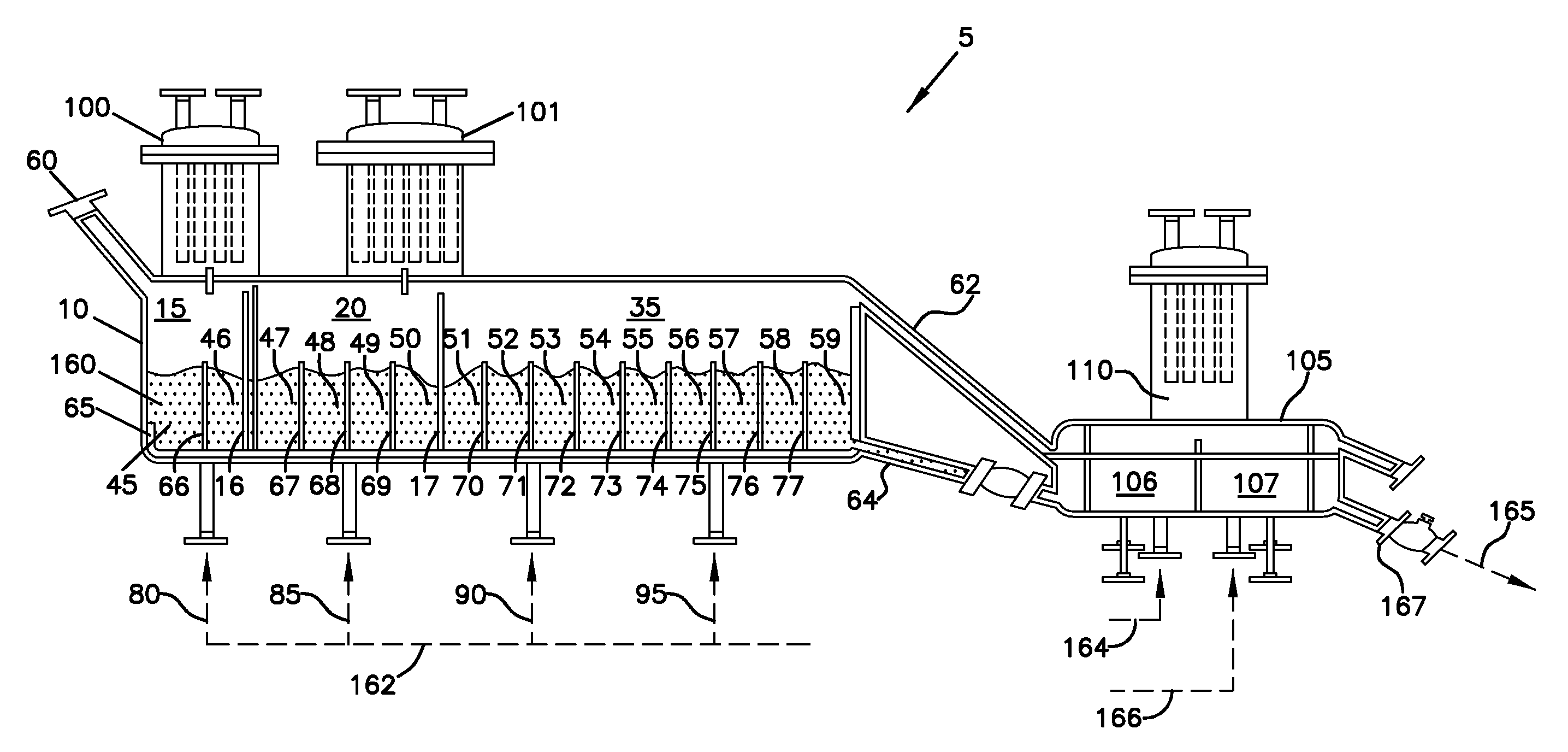
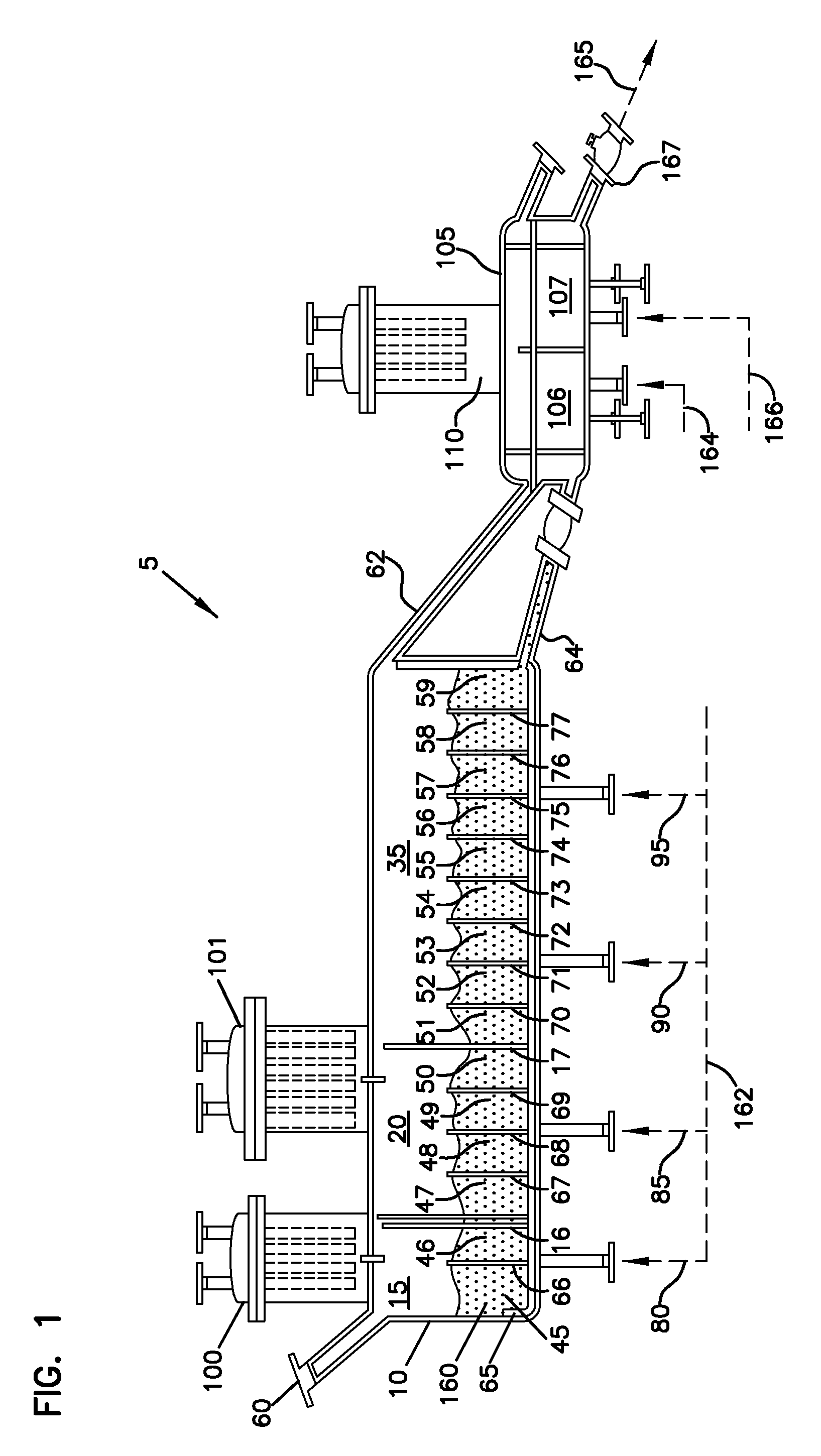
The patent describes a continuous calcination vessel and a catalyst preparation system, which can produce a continuous stream of calcinated chemically-treated solid oxide. This solid oxide can be used to make catalysts for the polymerization of olefins, resulting in the production of various articles of manufacture. The technical effect of the patent is to provide a more efficient and continuous method for producing high-quality calambiguus oxide, which is a key ingredient in the production of catalysts for the polymerization of olefins.

Problems solved by technology

Additionally, the batch process requires a long time period for heating the vessel and its contents to the desired calcining temperature and, thereafter, cooling down to room temperature.

Method used


Image

  • Continuous preparation of calcined chemically-treated solid oxides
  • Continuous preparation of calcined chemically-treated solid oxides
  • Continuous preparation of calcined chemically-treated solid oxides

Examples


examples

[0205]The invention is further illustrated by the following examples, which are not to be construed in any way as imposing limitations to the scope of this invention. Various other aspects, embodiments, modifications, and equivalents thereof which, after reading the description herein, may suggest themselves to one of ordinary skill in the art without departing from the spirit of the present invention or the scope of the appended claims.

[0206]The sulfated alumina employed in the Examples was prepared in accordance with the following procedure. Bohemite was obtained from W.R. Grace Company under the designation “Alumina A” and having a surface area of about 300 m2 / g and a pore volume of about 1.3 mL / g. This material was obtained as a powder having an average particle size of about 100 microns. This material was impregnated to incipient wetness with an aqueous solution of ammonium sulfate to equal about 15% sulfate. This mixture was then placed in a flat pan and allowed to dry under v...

examples 1-5

Effect of Calcination Time on Polymerization Activity

[0211]At a calcination temperature of 600° C., the calcination time of sulfated alumina was varied from 15 minutes to 6 hours in Examples 1-5. Table I summarizes the catalyst activity for Examples 1-5, measured in grams of polymer produced per gram of calcined chemically-treated solid oxide per hour.

[0212]

TABLE ICatalyst Activity and Calcination Time for Examples 1-5.CalcinationCatalystExampleTimeActivity115 min7020230 min76633 1 hr72984 3 hr69095 6 hr8211

examples 6-9

Effect of Calcination Time on Polymerization Activity

[0213]At a calcination temperature of 600° C., the calcination time of sulfated alumina was varied from 2 to 6 hours in Examples 6-9. Table II summarizes the catalyst activity for Examples 6-9, measured in grams of polymer produced per gram of calcined chemically-treated solid oxide per hour. Example 6 was conducted in the same manner as Examples 1-5. Examples 7-9 were calcined in the manner described above, but in a larger batch calcination vessel.

[0214]

TABLE IICatalyst Activity and Calcination Time for Examples 6-9.CalcinationCatalystExampleTimeActivity66 hr888472 hr800084 hr866796 hr10000


PUM

PropertyMeasurementUnit
linear velocityaaaaaaaaaa
temperatureaaaaaaaaaa
temperaturesaaaaaaaaaa

Abstract

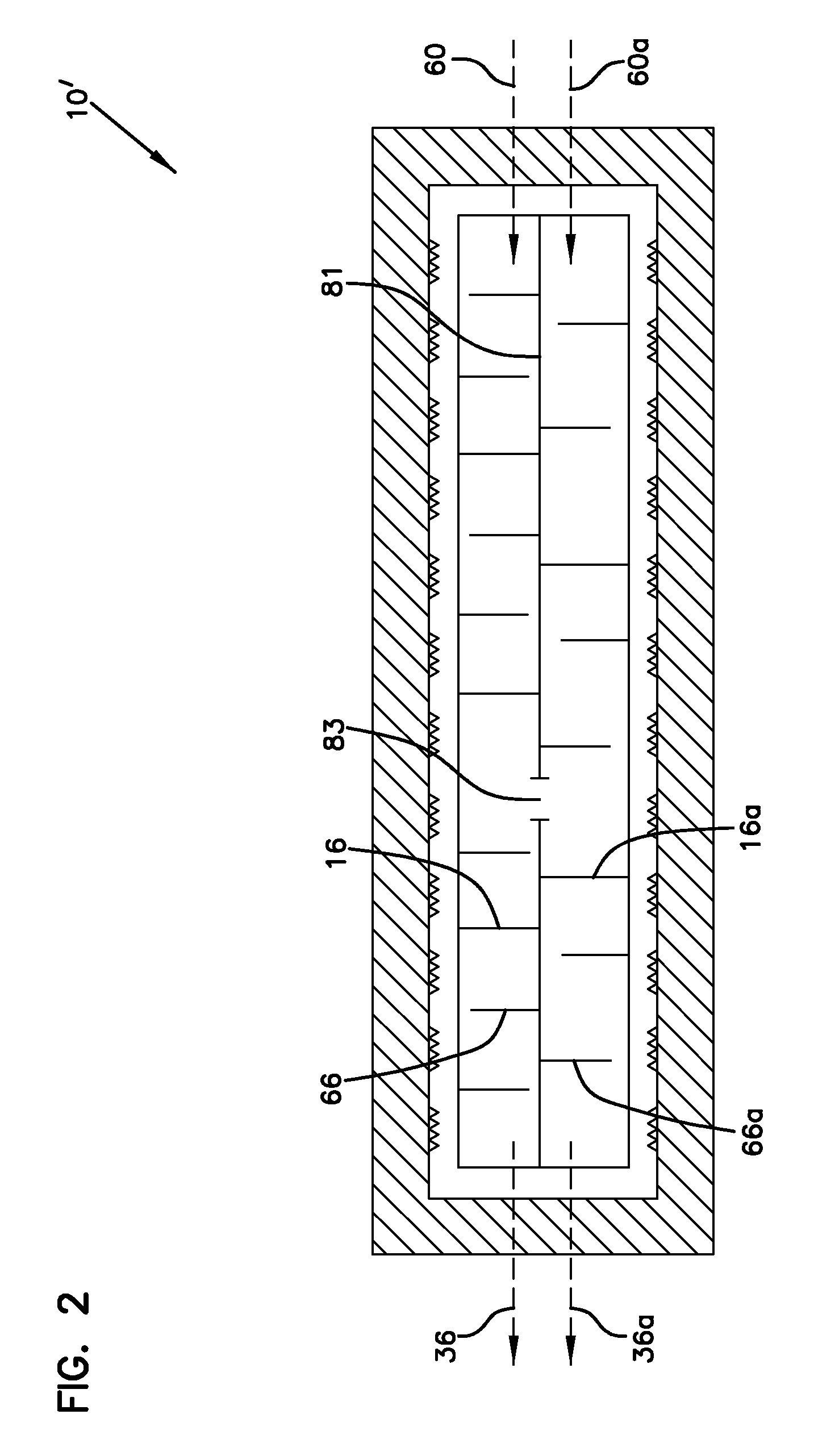
The present invention discloses a continuous calcination vessel which can be used to prepare calcined chemically-treated solid oxides from solid oxides and chemically-treated solid oxides. A process for the continuous preparation of calcined chemically-treated solid oxides is also provided. Calcined chemically-treated solid oxides disclosed herein can be used in catalyst compositions for the polymerization of olefins.

Description

BACKGROUND OF THE INVENTION[0001]The present invention relates generally to a continuous calcination vessel and to methods for continuously preparing calcined chemically-treated solid oxides. Such calcined chemically-treated solid oxides can be used in catalyst compositions for the polymerization of olefins.[0002]Often, a calcining step is required prior to utilizing a chemically-treated solid oxide in a catalyst composition and, subsequently, in a polymerization process to produce olefin-based polymers. Calcining can be accomplished in a batch process, which typically requires a large vessel which must be cycled from room temperature to temperatures of up to 700° C., and above, for each batch. Additionally, the batch process requires a long time period for heating the vessel and its contents to the desired calcining temperature and, thereafter, cooling down to room temperature. Hence, there exists a need for a calcination vessel and for a method of preparing calcined chemically-tre...

Claims


Application Information

Patent Timeline
Patent Type & Authority Patents(United States)
IPC IPC(8): B01J23/00B01J6/00B01J8/36B01J8/34B01J31/14B01J31/22
CPCB01J6/004B01J8/34B01J8/36B01J31/143B01J31/2295B01J2208/0053B01J2208/0084B01J2208/00176B01J2219/182B01J2531/48B01J8/1827B01J8/1836B01J2208/00548B01J2208/00938
Inventor BENHAM, ELIZABETH A.MCDANIEL, MAX P.
Owner CHEVRON PHILLIPS CHEMICAL CO LP
Learn More