Patient-based parameter generation systems for medical injection procedures

a patient-based parameter and parameter generation technology, applied in the field of patient-based parameter generation systems for medical injection procedures, can solve the problems of different image contrast and quality results, undeveloped parameters for the specific procedure of a specific patient, and injection profiles computed by inverse solution of the pk model are not readily realizable by most ct power injectors without major modification, so as to achieve the effect of reducing the volum

Active Publication Date: 2016-04-05
BAYER HEALTHCARE LLC
View PDF482 Cites 10 Cited by
  • Summary
  • Abstract
  • Description
  • Claims
  • Application Information

AI Technical Summary

Benefits of technology

[0020]The parameter generation system can determine whether the total volume of the pharmaceutical to be delivered to the patient in all phases exceeds the volume pharmaceutical available for delivery to the patient (for example, exceeds the volume of a container for the pharmaceutical from which pressurized pharmaceutical will be delivered to the patient). In such an embodiment, the parameter generation system can include rules to reduce the total volume of the pharmaceutical if the determined total volume exceeds the available volume. For example, the total volume can reduced so that the reduced total volume of the pharmaceutical to be delivered to the patient does not exceed the volume of a container from which the pharmaceutical is to be delivered.

Problems solved by technology

However, the manner in which such parameters are to be determined for a specific procedure for a specific patient are not well developed.
Although using standard, fixed or predetermined protocols (whether uniphasic, biphasic or multiphasic) for delivery simplifies the procedure, providing the same amount of contrast media to different patients under the same protocol can produce very different results in image contrast and quality.
However, the injection profiles computed by inverse solution of the PK model are profiles not readily realizable by most CT power injectors without major modification.
Uniphasic administration of contrast agent (typically, 100 to 150 mL of contrast at one flow rate) results in a non-uniform enhancement curve.
A fundamental difficulty with controlling the presentation of CT contrast agent is that hyperosmolar drug diffuses quickly from the central blood compartment.
Because the method of Fleischmann et. al. computes input signals that are not realizable in reality as a result of injection system limitations (for example, flow rate limitations), one must truncate and approximate the computed continuous time signal.
In addition to potential hazards to the patient (for example, vessel damage) and potential degradation of the diagnostic and / or therapeutic utility of the injection fluid, excessive pressure can lead to equipment failure.
If the injector causes pressure in the fluid path to rise above the burst strength of a disposable fluid path element, the fluid path element will fail.
In addition to problems of control with current injector systems, many such systems lack convenience and flexibility in the manner in which the injector systems must be operated.

Method used


Image

  • Patient-based parameter generation systems for medical injection procedures
  • Patient-based parameter generation systems for medical injection procedures
  • Patient-based parameter generation systems for medical injection procedures

Examples


Embodiment Construction

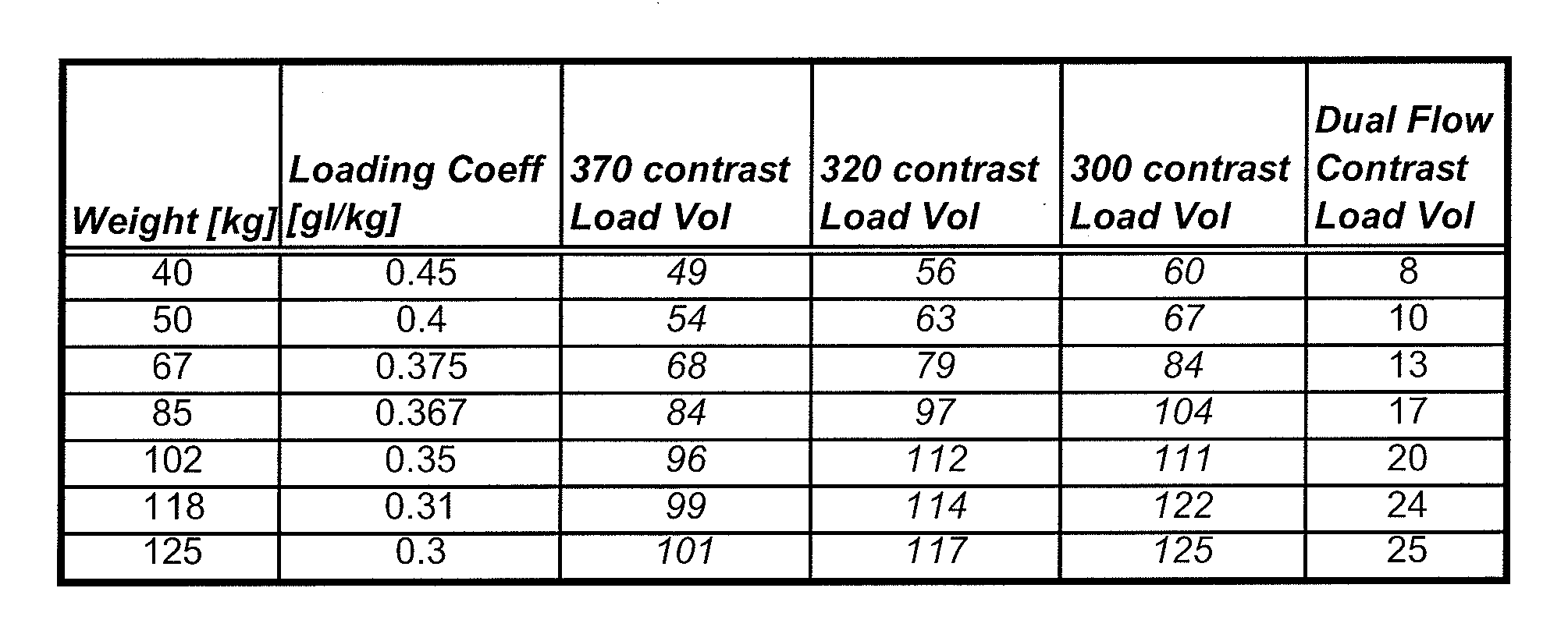
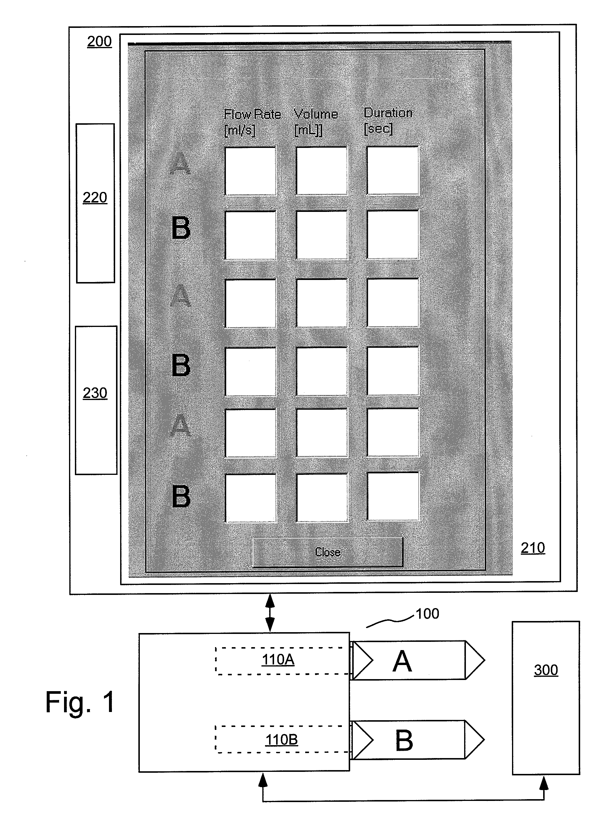
[0108]As used herein with respect to an injection procedure, the term “protocol” refers to a group of parameters such as flow rate, volume injected, duration etc. that define the amount of fluid(s) to be delivered to a patient during an injection procedure. Such parameters can change over the course of the injection procedure. As used herein, the term “phase” refers generally to a group of parameters that define the amount of fluid(s) to be delivered to a patient during a period of time (or phase duration) that can be less than the total duration of the injection procedure. Thus, the parameters of a phase provide a description of the injection over a time instance corresponding to the time duration of the phase. An injection protocol for a particular injection procedure can, for example, be described as uniphasic (a single phase), biphasic (two phases) or multiphasic (two or more phases, but typically more than two phases). Multiphasic injections also include injections in which the...


PUM


Abstract

A system includes a parameter generation system to determine parameters of at least one phase of an injection procedure based at least in part upon a type of the injection procedure. The parameter generator system determines the amount of a pharmaceutical that is to be delivered to a patient at least in part on the basis of the concentration of an agent in the pharmaceutical and at least on part on the basis of a function that depends upon and varies with a patient parameter. The patient parameter can, for example, be weight, body mass index, body surface area or cardiac output. The pharmaceutical can, for example, include a contrast enhancing agent for use in an imaging procedure.

Description

CROSS-REFERENCE TO RELATED APPLICATION[0001]This application claims benefit of PCT Application US07 / 026194, filed Dec. 21, 2007 and U.S. Provisional Application Ser. No. 60 / 877,779, filed on Dec. 29, 2006, and U.S. Provisional Patent Application Ser. No. 60 / 976,002, filed Sep. 28, 2007, the contents of which are hereby incorporated by reference.RELATED APPLICATIONS[0002]This application contains subject matter that may be related to that disclosed and / or claimed in Published PCT Application No. WO / 2006 / 058280 (PCT International Patent Application No. PCT / US05 / 042891), filed on Nov. 23, 2005 and Published PCT Application No. WO / 2006 / 055813 (PCT International Patent Application No. PCT / US2005 / 041913), filed on Nov. 16, 2005, the disclosures of which are incorporated herein by reference and made a part hereof.BACKGROUND OF THE INVENTION[0003]The present invention is related to devices, systems and methods for fluid delivery, and, particularly, to devices, systems and methods for delive...

Claims


Application Information

Patent Timeline
Patent Type & Authority Patents(United States)
IPC IPC(8): A61B5/00A61M5/172G06F19/00A61M5/00A61M5/142A61B6/00G16H20/17
CPCA61M5/172G06F19/3468A61B6/507A61M5/007A61M2005/14208G16H40/63G16H30/40G16H20/13G16H20/17A61B6/032A61B6/037A61B6/544A61B8/481A61M5/1452A61M5/1723A61M2230/04
Inventor KALAFUT, JOHNMCCUTCHAN, LARRYCOSGROVE, ERIN
Owner BAYER HEALTHCARE LLC
Why Eureka
Try Eureka