Heat treatment method of pin for endless track

a technology of endless track and heat treatment method, which is applied in the direction of heat treatment furnaces, heat treatment equipment, furnaces, etc., can solve the problems of increased inability to obtain necessary wear resistance and strength, and increase the cost of carburizing gas, so as to reduce manufacturing costs and reduce the effect of high compressive residual stress and improved productivity

Inactive Publication Date: 2016-04-05
TOPY INDUSTRIES
View PDF10 Cites 2 Cited by
  • Summary
  • Abstract
  • Description
  • Claims
  • Application Information

AI Technical Summary

Benefits of technology

[0048]In the prior art, four steps are necessary for a heat treatment of a columnar work. By means of the present invention including the above-mentioned constitutions, number of steps being required for the heat treatment of the columnar work (3) are reduced to three steps, and therefore, a productivity is improved and manufacturing costs are reduced.
[0049]Further, since the outer circumferential surface region (31) of the columnar work (3) is merely quench-hardened in the second quench-hardening step (S12), a high compressive residual stress is generated on the outer circumferential surface region (31), thereby the fatigue strength of the columnar work (3) is improved.
[0050]In addition, since a hardness of an region near a position, at which the maximum shearing stress in cross-section of the pin is generated, is increased as compared with one in the prior art, it is possible to prevent fracture even if an excessive shearing stress is imposed thereon. Accordingly, it is not necessary to use a raw material having high hardenabilily for securing a required hardness of the core portion, so that a raw material with less addition (in amounts) of alloy elements can be used as a raw material to be carried out, and cost for buying raw materials can be reduced.
[0051]Here, in the present invention, in a case that the partial region of the columnar work (3) being from the outer circumferential surface (31f) to the core (32) is heated to the temperature not lower than the transformation temperature Ac3 and then the work (3) is quench-hardened in the first quench-hardening step (S11A), in such the case the entire region of the cross section of the columnar work (3) is not heated to the temperature not lower than the transformation temperature Ac3, since it is not necessary to heat the entire region of the cross section of the columnar work (3) to the temperature not lower than the transformation temperature Ac3, a heating time in the first quench-hardening step (S11A) can be shortened.
[0052]As a result, energy consumed amount for heating in the first quench-hardening step (S11A) can be reduced.
[0053]In the present invention, in a case that an induction heating is carried out for heating in the first quench-hardening step (S11), it is possible to carry out the quench-hardening step (S1) in a continuous manner.

Problems solved by technology

However, in a method for carburizing and quench-hardening, in order to increase a wear resistance and a strength of a pin, it is necessary to increase a carburized case depth, and to extend a carburizing time, and thereby, there is a problem that a cost is increased.
Also, there is a problem that a large quantity of a carburizing gas should be necessary, and then, a cost for the carburizing gas is increased.
However, in the above-mentioned prior art, since the quench-hardened layer depth of the pin is dependent on hardenability of the raw material, a diameter of the pin and so on, a necessary wear resistance and a strength will not be obtained in a case that a raw material having low hardenability is used.
On the other hand, in a case that a raw material having high hardenability is used, an excessive increase in the quench-hardened layer depth of the pin will be happened, and thereby, a compressive residual stress on the outer circumferential surface of the pin will be decreased, so that there will be a problem of a decreasing a fracture toughness and a fatigue strength of the pin.
In the above-mentioned prior art, in which steps of “the first step of thermal refining, that is, a quench-hardening”, “the second step of thermal refining, that is, high-temperature tempering”, the high-frequency induction hardening, and the low-temperature tempering are carried out, since four steps should be carried out, there is a problem that a lead time will be longer, and thereby, a entire processing time will be longer.
However, since such the raw material is expensive, a cost will be increased.
In addition, in case that the necessary hardness of the core (hardness of the core portion) cannot be obtained, there is a possibility that the pin is broken upon being imposed an excessive shearing stress thereon.
However, in the above-mentioned prior art (Patent Document 1), there is a problem that a depth of the secondary quench-hardened layer is on the order of 0.5 mm to 0.7 mm, and then, a satisfactory wear resistance being required for a pin for an endless track cannot be embodied.

Method used


Image

  • Heat treatment method of pin for endless track
  • Heat treatment method of pin for endless track
  • Heat treatment method of pin for endless track

Examples


first embodiment

[0064]The method according to the present invention is described hereinafter with reference to FIGS. 1 to 7.

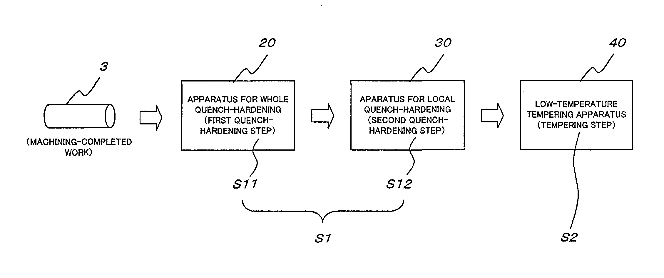
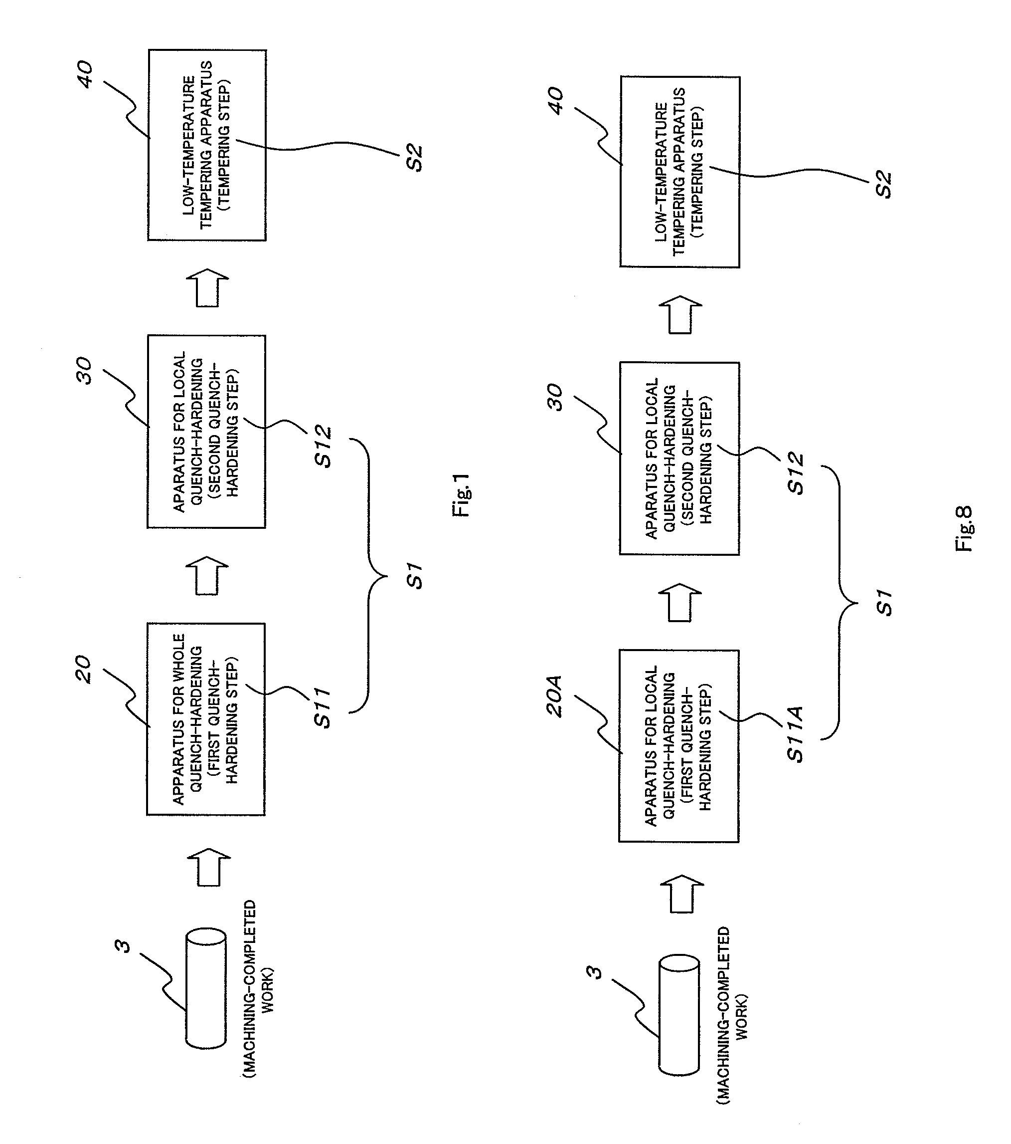
[0065]In the method according to the first embodiment, the large-sized pin 3 is manufactured according to steps of a flow sheet shown in FIG. 1, after completion of machining.

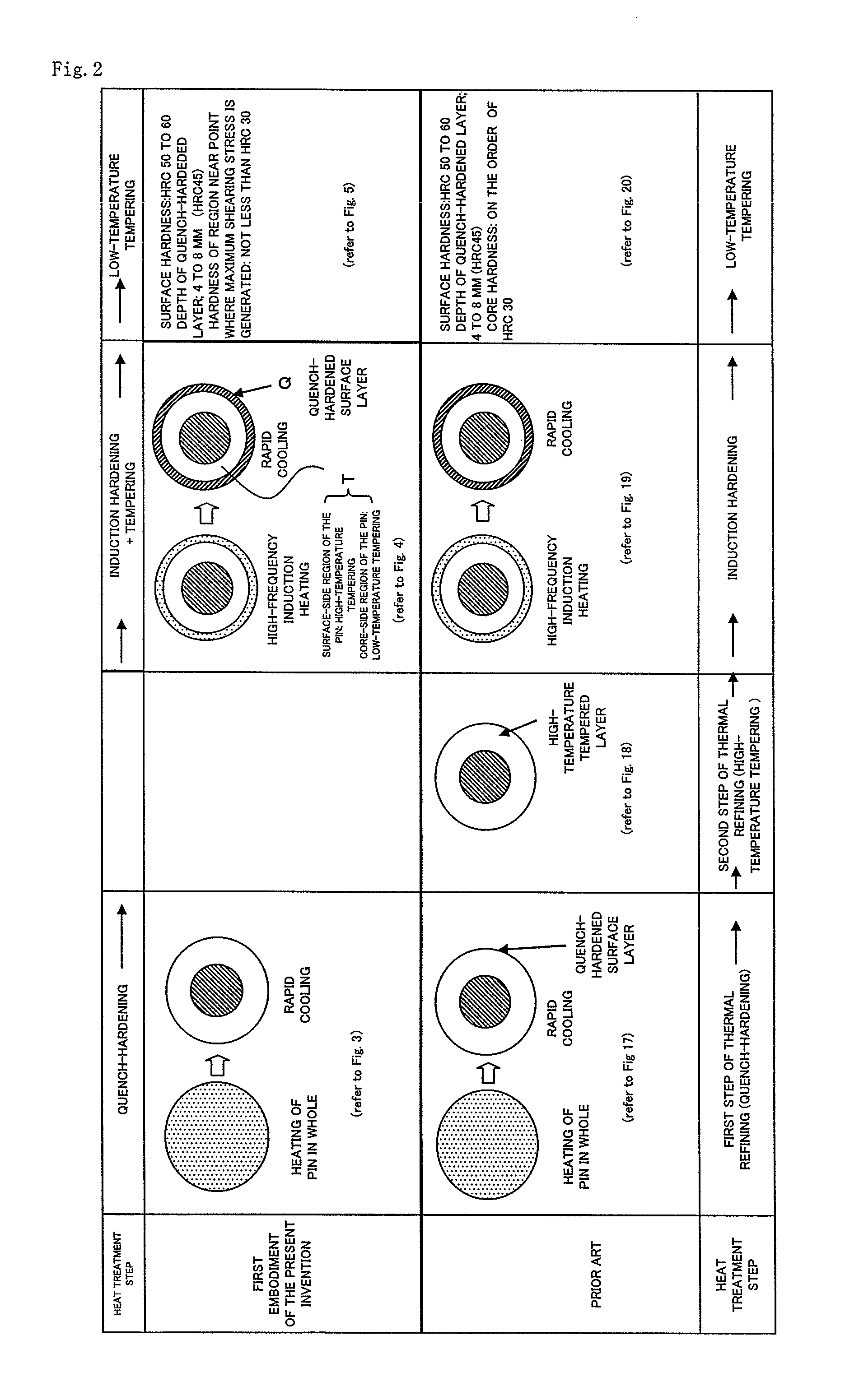
[0066]FIG. 2 shows the method according to the first embodiment of the present invention in comparison with the prior art (the prior art wherein the first step of thermal refining, that is, a quench-hardening, the second step of thermal refining, that is, high-temperature tempering, the high-frequency induction hardening, and the low temperature tempering are carried out) described with reference to FIGS. 17 to 20. More specifically, in FIG. 2, there are schematically shown metallic microstructures of the pin, in cross section, in respective steps (manufacturing processes) of the method according to the first embodiment of the present invention in comparison with metallic microstructures of the pin, in cr...

second embodiment

[0121]Next, the present invention is described hereinafter with reference to FIGS. 8 to 12.

[0122]In the second embodiment as well, heat treatment is carried out to a pin as a constructional part of the endless track 10 (refer to FIG. 13) for use in, for example, the construction vehicle, such as an excavator, bulldozer, and so on.

[0123]In a method according to the second embodiment as well, a large-sized pin as large as 50 mm or more in diameter is cited by way of example, however, the method according to the second embodiment is applicable to a small-sized pin, and a medium-sized pin, as well.

[0124]In the method according to the second embodiment of the present invention, a large-sized pin 3 is manufactured according to steps of a flow sheet shown in FIG. 8, after completion of machining.

[0125]FIG. 9 shows the method according to the second embodiment of the present invention in comparison with the prior art (the prior art in which the first step of thermal refining, that is, a que...


PUM

PropertyMeasurementUnit
diameteraaaaaaaaaa
lengthaaaaaaaaaa
lengthaaaaaaaaaa

Abstract

The present invention relates to a method for heat treatment of a columnar work. In order to provide the method for heat treatment of a columnar work being able to attain a high productivity, a reduction of cost, and an improvement of quality, as compared with the prior art, the method for heat treatment of a columnar work of the present invention includes a quench-hardening step (S1) and a tempering step (S2) being carried out after the quench-hardening step (S1), the quench-hardening step (S1) includes a first quench-hardening step (S11) and a second quench-hardening step (S12) being carried out after the first quench-hardening step (S11), the entire region of the columnar work (3) from an outer circumferential surface (31f) to a core thereof (32), or a partial region thereof, is heated up to a temperature not lower than a transformation temperature Ac3, and then, the work is quench-hardened.

Description

TECHNICAL FIELD[0001]The present invention relates to a method for heat treatment of a columnar work, in particular, a large-sized (large-diameter) columnar work. In this connection, “a columnar work” includes a pin as a constructional part of an endless track of, for example, a construction vehicle. However, “a columnar work” is limited to neither a pin, nor a large-sized work (a pin being large in diameter, in a case that the work is a pin).BACKGROUND ART[0002]An endless track 10 (refer to FIG. 13) used for a construction vehicle, such as an excavator, bulldozer, and so on, comprises a pair of links 1, a shoe 2, a pin 3, and a bushing 4, as shown in FIG. 14.[0003]In FIG. 15, a columnar work such as a pin 3 used for an endless track, in an outer circumferential surface region 31 thereof (an outer circumferential surface, and a region in the vicinity thereof), is required so as to have a strength being capable for withstanding bending stress and torsion stress, and wear resistance, ...

Claims


Application Information

Patent Timeline
Patent Type & Authority Patents(United States)
IPC IPC(8): C21D1/42B62D55/21C21D1/00C21D1/06C21D1/10C21D1/18C21D9/00C21D9/08C22C38/02C22C38/04C22C38/22
CPCB62D55/211C21D1/06C21D1/10C21D1/18C21D1/42C21D9/0075C21D9/0093C21D9/08C21D2211/008C22C38/02C22C38/04C22C38/22C21D1/25C21D1/78C21D2221/10C21D9/0068Y02P10/25
Inventor XUE, WEIDONG
Owner TOPY INDUSTRIES
Why Eureka
Try Eureka