Utility vehicle

a technology for utility vehicles and vehicles, applied in the field of utility vehicles, can solve problems such as troublesome work, and achieve the effects of convenient operation, convenient fuel supply, and balanced seat fram

Active Publication Date: 2016-04-12
KAWASAKI MOTORS LTD
View PDF5 Cites 5 Cited by
  • Summary
  • Abstract
  • Description
  • Claims
  • Application Information

AI Technical Summary

Benefits of technology

[0010](a) The fuel system mounting bracket is bridged between upper and lower frame members of the seat frame. In this configuration, the fuel system mounting bracket can serve as a constituent member of the seat frame and rigidity of the seat frame can be balanced.
[0011](b) The fuel tank is located at an end in a vehicle width direction in the lower space, and the fuel feed pump and the single or the plurality of fuel system accessories are located closer to a center in the vehicle width direction than the fuel tank. This configuration make it possible to direct a fuel supply port of the fuel tank to outside the vehicle. Therefore, the fuel supply port is easily accessible from a lateral side of the vehicle and a fuel supply task is thus facilitated. Furthermore, the fuel feed pump and the fuel system accessory can be protected by the fuel tank located close to an end in the vehicle width direction.
[0012](c) The single or the plurality of fuel system accessories includes at least one of a fuel filter and a fuel-water separator. This configuration facilitates the task

Problems solved by technology

When a fuel feed pump and a fuel system accessory are mounted to an engine or a chassis frame by way of different brackets, the fuel feed pump a

Method used


Image

  • Utility vehicle
  • Utility vehicle
  • Utility vehicle

Examples


Embodiment Construction

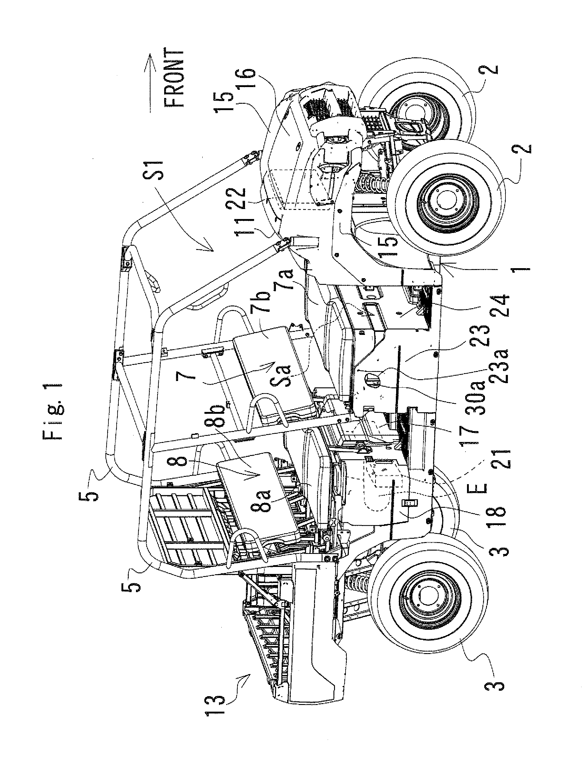
[0024]FIGS. 1 to 7 show a utility vehicle according to the present invention. A preferred embodiment of the present invention will now be described with reference to these figures. For convenience of description in this embodiment, a forward travelling direction of the vehicle is called “front” of the vehicle and each of components of the vehicle, and a right and left direction as seen from a driver or passenger is called “a right and left direction” of the vehicle and each of the components of the vehicle.

[0025]FIG. 1 is a perspective view of the entire utility vehicle. The utility vehicle includes a chassis frame 1, right and left front wheels 2 located at a front end of the chassis frame 1, and right and left rear wheels 3 located at a rear end of the chassis frame 1. A cabin (riding space) S1 is located between the front wheels 2 and the rear wheels 3 in a front-rear direction, and is surrounded with a R.O.P.S. 5. The cabin S1 accommodates a bench type front sheet 7 and a bench ...


PUM


Abstract

The present invention provides a utility vehicle including fuel system components located compactly. The utility vehicle includes a single or a plurality of seat rows, a cargo bed, a cabin, and an engine. The utility vehicle further includes a fuel tank accommodated in a lower space of one of the seat rows, a fuel system mounting bracket provided next to the fuel tank in the lower space and fixed to a seat frame, and a fuel feed pump and a single or a plurality of fuel system accessories mounted to the fuel system mounting bracket.

Description

BACKGROUND OF THE INVENTION[0001]1. Field of the Invention[0002]The present invention relates to a utility vehicle, and particularly to location of a fuel tank, a fuel feed pump, and a single or a plurality of fuel system accessories.[0003]2. Description of the Prior Art[0004]In a utility vehicle equipped with a gasoline engine, a fuel feed pump is typically located in a fuel tank. On the other hand, in a utility vehicle equipped with a diesel engine, a fuel feed pump is located outside a fuel tank and on a fuel supply path. A fuel feed pump located outside a fuel tank is mounted to a chassis frame or an engine by way of a pump mounting bracket that is provided separately from a mounting bracket for a fuel system accessory.[0005]When a fuel feed pump and a fuel system accessory are mounted to an engine or a chassis frame by way of different brackets, the fuel feed pump and the fuel system accessory need to be mounted or demounted individually for mounting, demounting or maintaining,...

Claims


Application Information

Patent Timeline
IPC IPC(8): B60K15/063B60K15/03F02M37/14F02M37/22B60K15/035B60K15/01F02M37/24F02M37/32F02M37/54
CPCB60K15/03006F02M37/14F02M37/221B60K15/035B60K15/01B60K2015/03243B60K2015/03236F02M37/0011F02M37/20B60K15/063B60K2015/0632B60K2015/0633B60Y2200/23F02M37/24F02M37/54F02M37/32
Inventor EGAMI, KOICHINOZAKI, TAKUMAOHSHITA, YUJITAKAGI, JUNORIHASHI, YOSHIHIKOFUKUUCHI, MASASHI
Owner KAWASAKI MOTORS LTD
Why Eureka
Try Eureka