Aircraft engine module handling assembly

a technology for handling assembly and aircraft engine, which is applied in the direction of lifting devices, transportation and packaging, manufacturing tools, etc., can solve the problems of long and difficult handling operation, many precautions, and delicate operation, and achieve the effect of no longer being subject to any risk of tipping

Active Publication Date: 2016-04-12
SN DETUDE & DE CONSTR DE MOTEURS DAVIATION S N E C M A
View PDF30 Cites 34 Cited by
  • Summary
  • Abstract
  • Description
  • Claims
  • Application Information

AI Technical Summary

Benefits of technology

[0011]Assembly can be accomplished by releasing the module from the carriage, and by raising it by means of a hoist. The handling assembly can then be completed by a lifting arm which extends from one end to the other of the module, attached for example to the module by one end, and to the tooling by the other end, and fitted with attachment means which enable it to be raised at the centre of gravity of the module, which is therefore no longer subject to any risk of tipping.

Problems solved by technology

This handling operation is long and difficult since aircraft engine modules are bulky and heavy items, whilst also being fragile.
A particular difficulty derives from the fact that they are generally assembled with their rotational axis horizontal, whereas they are often positioned with the rotational axis vertical during shipment in their crate, in order that they are resting on a surface with a flat end, and in order that stability during shipment is improved: they must therefore be overturned when they have been removed from the crate, normally before being positioned on the carriage, but this operation is delicate and therefore requires many precautions.
Placing the module on the carriage is also a delicate operation, and special brackets must be added to the module, called “lugs”, to enable it to rest on it in stable fashion and with sufficient area, which would otherwise be impossible due to its generally conical and irregular rotational shape.

Method used


Image

  • Aircraft engine module handling assembly
  • Aircraft engine module handling assembly
  • Aircraft engine module handling assembly

Examples


Embodiment Construction

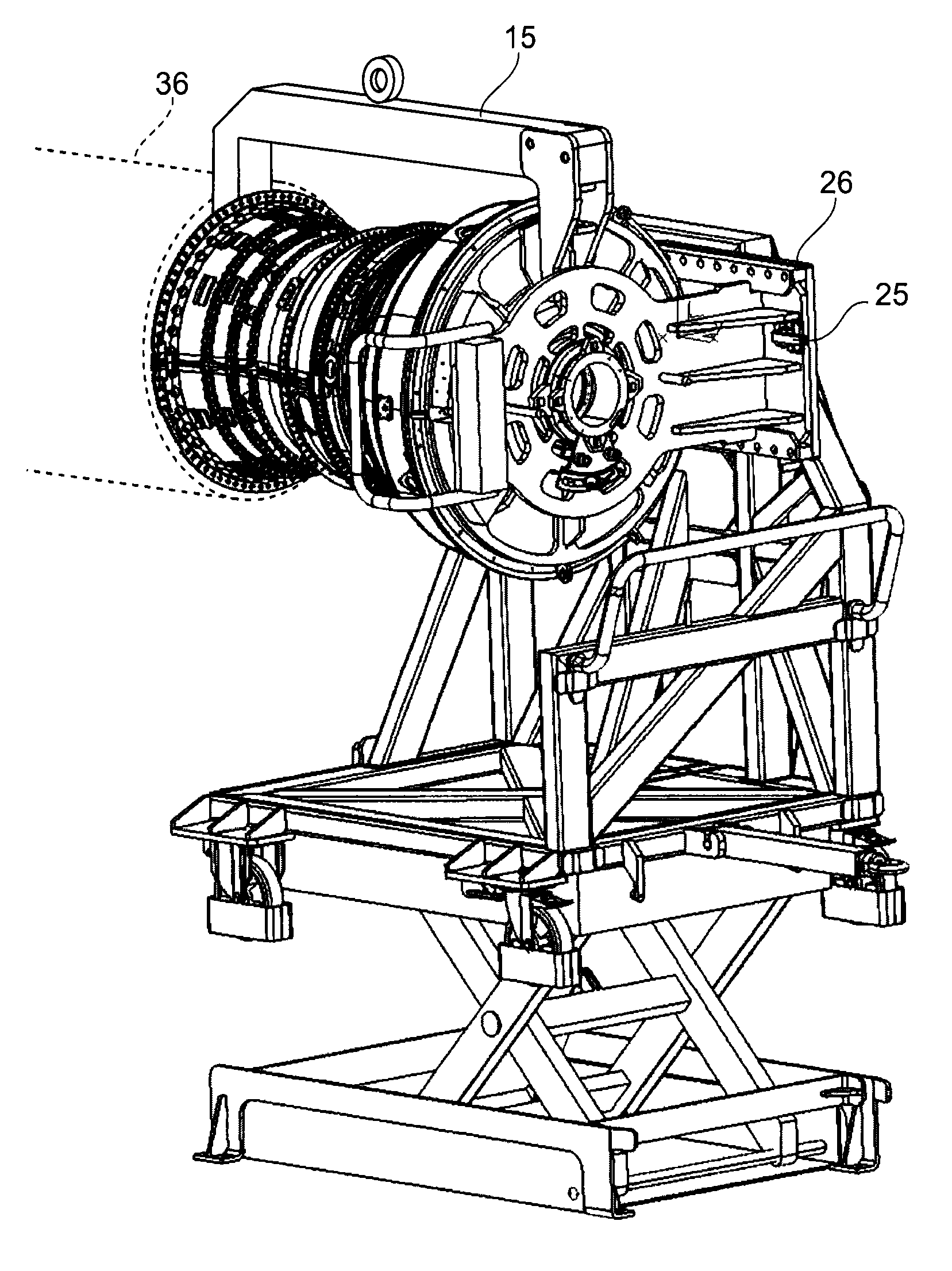
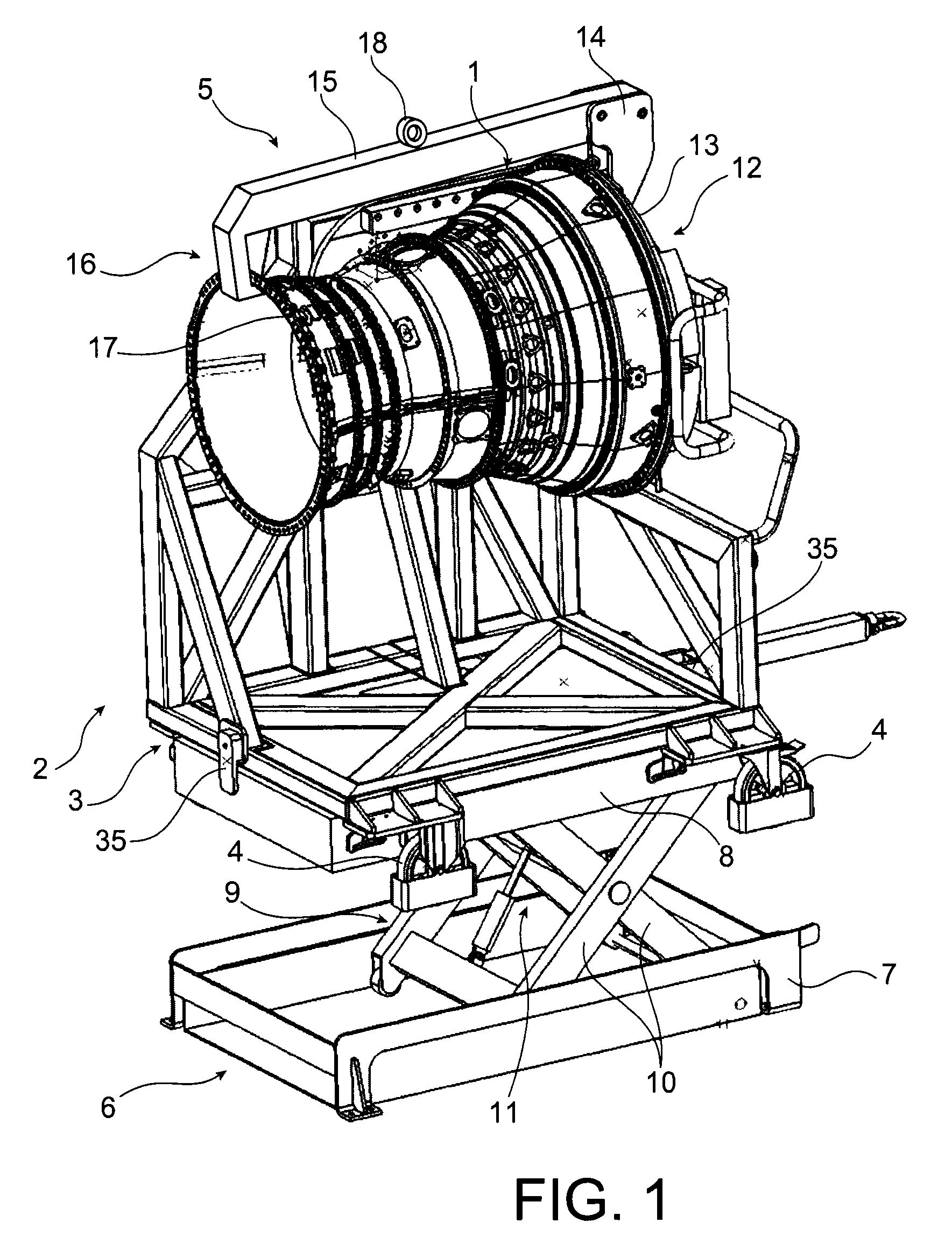
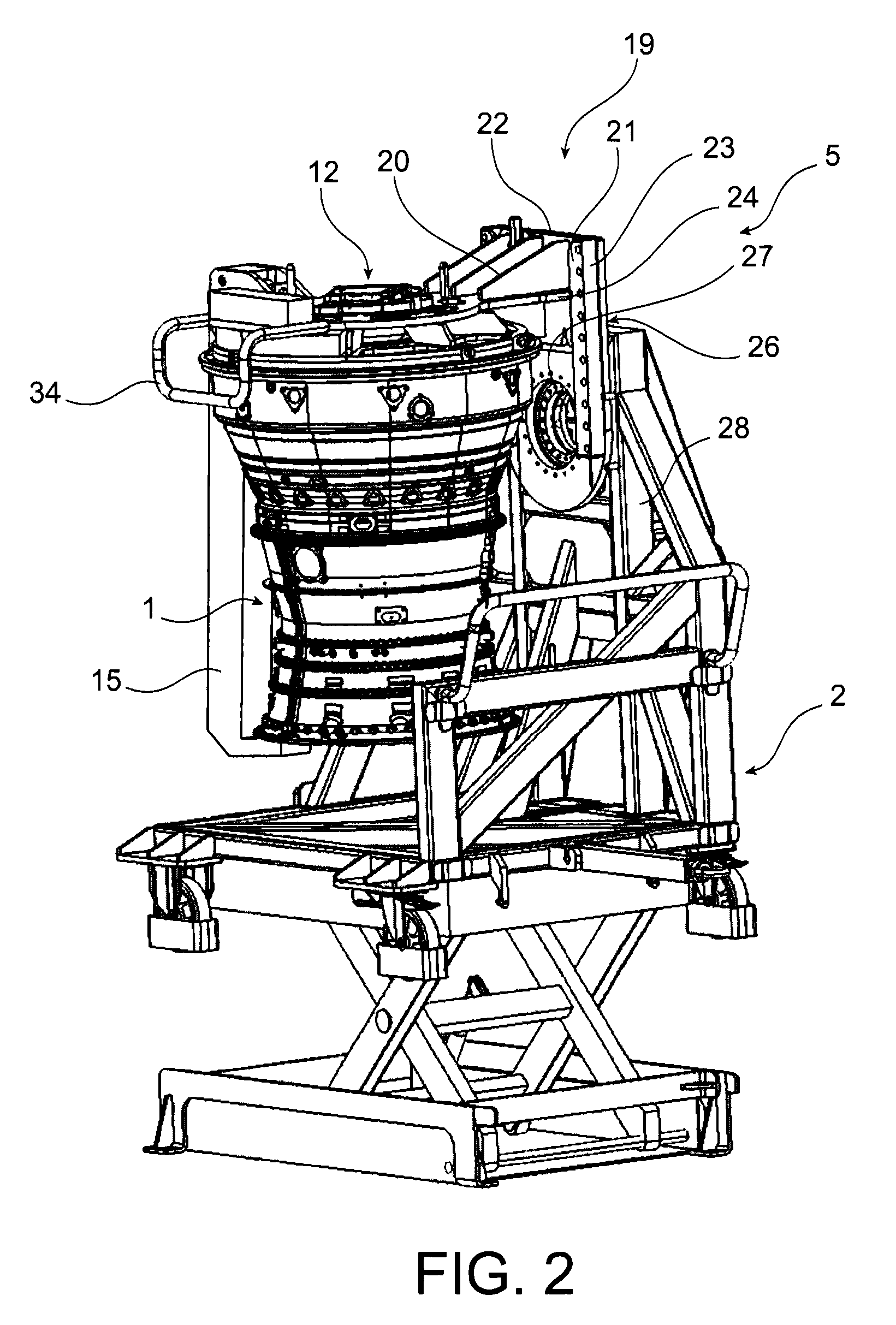
[0017]Aircraft engine module 1, which appears in this embodiment of the invention, is called the “core”, or high-pressure body. This is a major intermediate module including the compressor and the high-pressure turbine, and the combustion chamber. As can be seen in FIGS. 1 to 3, it is assembled on a carriage 2 including a frame 3, rollers 4 installed on frame 3 and a reinforcement structure 5 rising from frame 3 and bearing module 1. Carriage 2 is however raised from the ground and borne by a lifting device 6 including a frame 7 and, above all, positioned in frame 7, an upper table 8 on which frame 3 of carriage 2 is installed, and a mechanism 9 with bars 10 connected by their middle, positioned between table 8 and the ground, and which raises this table when the angle of connection of bars 10 is modified by a jack 11. Another element of the assembly is tooling 12 taking the appearance of a cover attached to the rear of a cover 1: this is originally a “strongback”, known in the art ...


PUM


Abstract

An aircraft engine module handling assembly including a carriage, a pivoting portion at a top of the carriage, a module support tooling, and an additional mechanism for assembly of the tooling on the pivoting portion, such that the module can be rotated from an original vertical position, observed when it reaches an assembly shop in a crate, to a horizontal position suitable for its assembly with another module of an engine.

Description

BACKGROUND OF THE INVENTION[0001]1. Field of the Invention[0002]The present invention relates to an aircraft engine handling assembly.[0003]2. Description of the Related Art[0004]Aircraft engines are firstly manufactured in separate modules, which are then assembled with one another. The manufactured modules are transported to the place of assembly, and then removed from their conditioning and moved precisely to the position in which they are docked with the adjacent module. The movements are essentially accomplished by handling, although plant such as hoists to raise the modules, and carriages to move them, are available.[0005]This handling operation is long and difficult since aircraft engine modules are bulky and heavy items, whilst also being fragile. A particular difficulty derives from the fact that they are generally assembled with their rotational axis horizontal, whereas they are often positioned with the rotational axis vertical during shipment in their crate, in order tha...

Claims


Application Information

Patent Timeline
Patent Type & Authority Patents(United States)
IPC IPC(8): B23Q1/00B66F9/06B64F5/00B66F7/06
CPCB64F5/0036B66F7/065B66F7/0625B66F9/06B64F5/50
Inventor BOULANGER, PASCALDAVID, DANIELEARITH, THOMAS JULIEN ROLANDMARCHAND, JACQUES
Owner SN DETUDE & DE CONSTR DE MOTEURS DAVIATION S N E C M A
Why Eureka
Try Eureka