
Ocean wave kinetic energy conversion method and system

a technology of kinetic energy and ocean wave, applied in the field of subsea water turbines, can solve the problems of limiting the effective usable area of the turbine installation, inefficient electric generation, and low speed of the two-bladed savonius rotor, and achieves high inertia, favorable longevity, and durable construction

Active Publication Date: 2016-04-12
GAUL ROY D +3
View PDF21 Cites 10 Cited by
  • Summary
  • Abstract
  • Description
  • Claims
  • Application Information

AI Technical Summary

Benefits of technology

The patent describes a device called a water flow diverting ramp that is placed on the seabed in front of a water turbine. This ramp has a curved surface that helps to speed up the flow of water away from the coast to increase power production. The ramp is designed to have no effect on the rotation and power production of the turbine when the water is flowing in the opposite direction. The technical effect of this device is to increase the amount of power that can be generated from waves in the ocean. Additionally, the device is designed to be safe and compatible with recreational activities in the ocean.

Problems solved by technology

Thus, the vertical axis Savonius rotor can use wind from any and all directions at all times. A two-bladed Savonius rotor typically operates at relatively low speeds in comparison to some other types of rotors and has usually been considered to be inefficient for electric generating purposes.
There are several problems associated with turbines disposed in these locations.
In a river, there are competing users of the water stream, such as boats, fishing vessels, bridges, etc., which may limit the effective usable area for a turbine installation.
There may also be various types of suspended particles, debris, and materials, such as sand, rocks, and ice, in the waterway that could damage or adversely affect the operation of the turbine, as well as sea life in the vicinity that could raise environmental concerns or prohibit placement of a turbine in the waterway.

Method used


Image

  • Ocean wave kinetic energy conversion method and system
  • Ocean wave kinetic energy conversion method and system
  • Ocean wave kinetic energy conversion method and system

Examples


Embodiment Construction

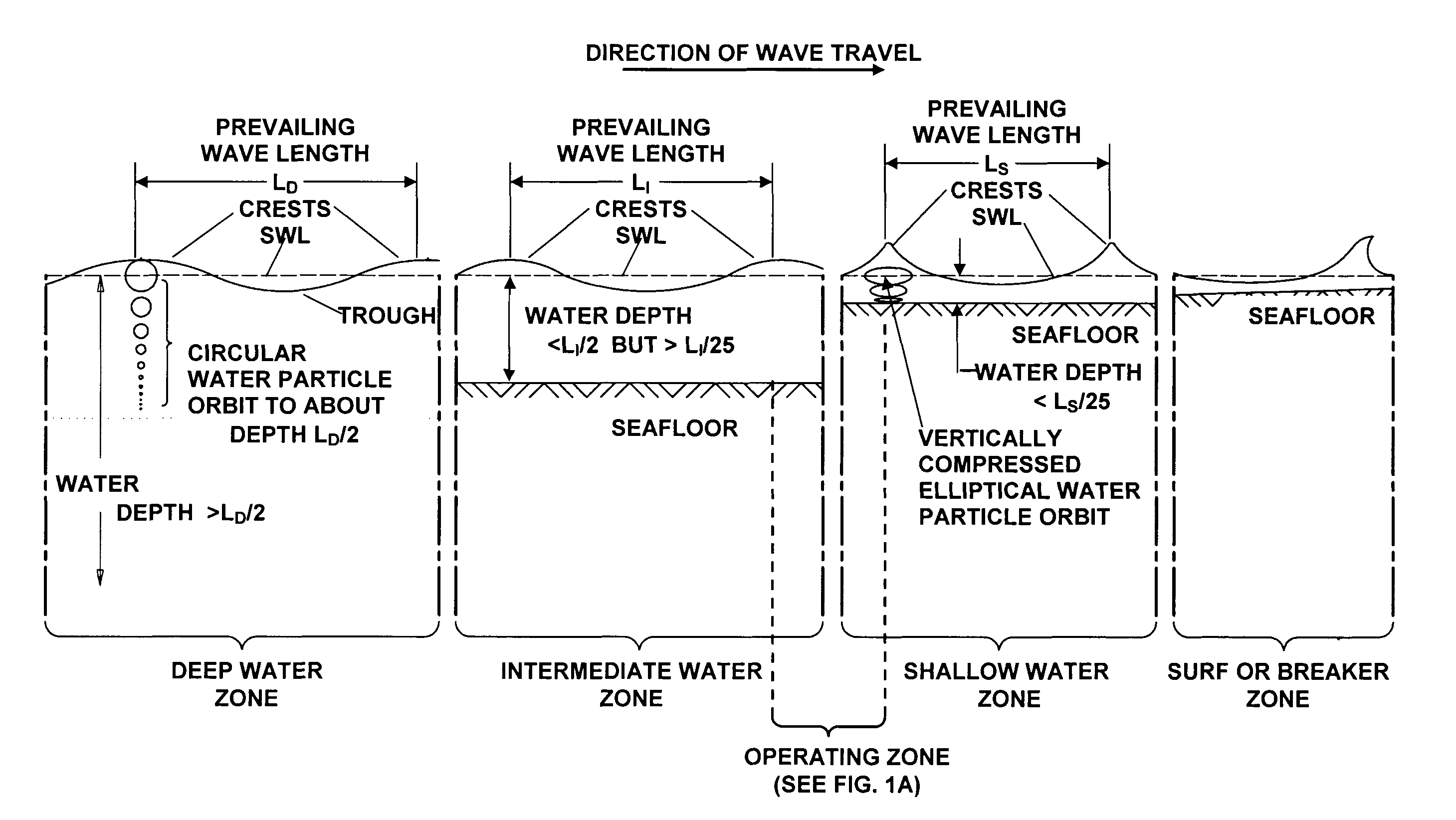
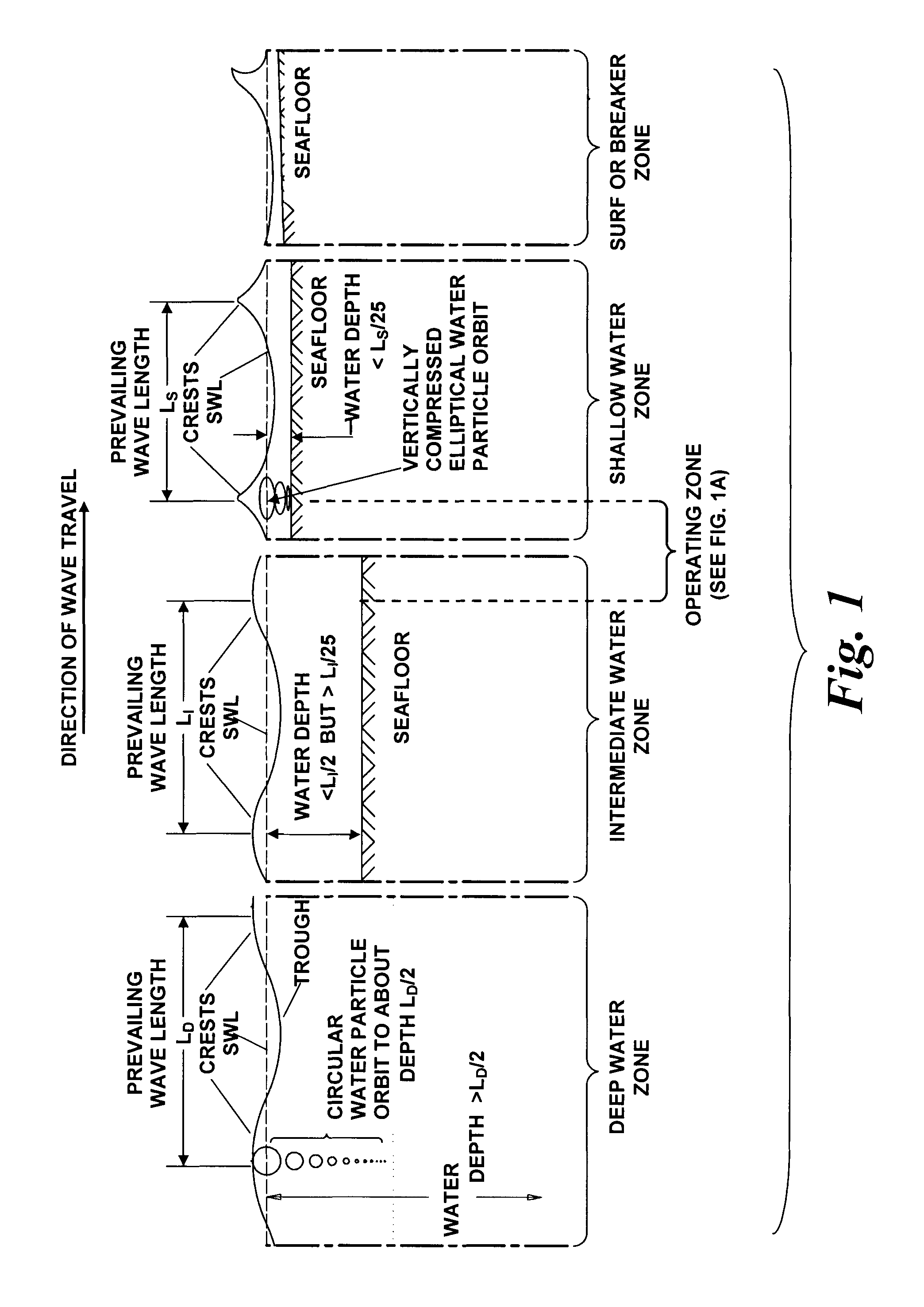
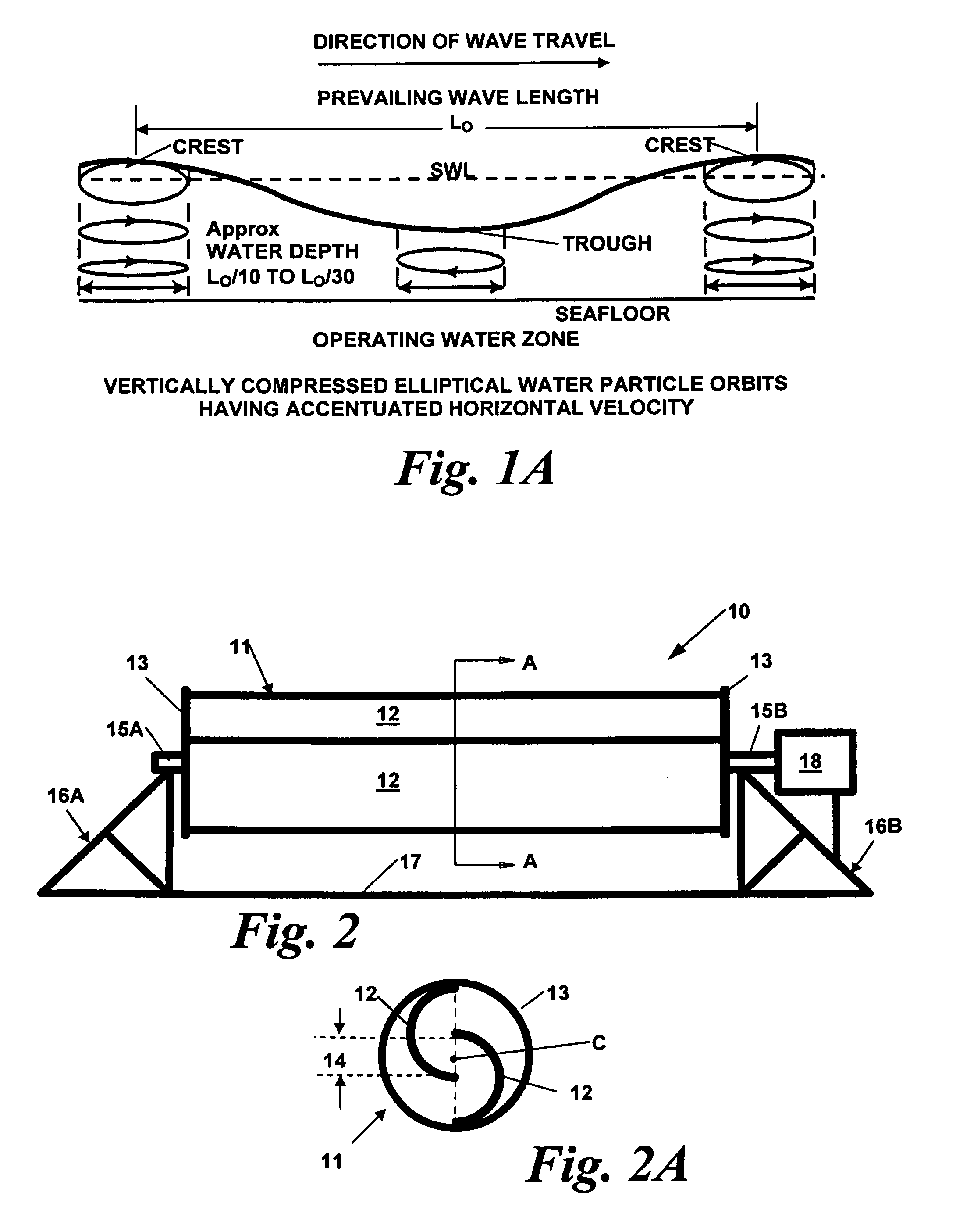
[0075]The present invention is directed toward a method of producing electrical power from kinetic energy of oscillatory water motion caused by ocean waves approaching a coastline. The preferred mechanism for conversion of the energy is a system utilizing horizontal axis rotor turbine apparatus, mounted on a foundation affixed to or on the seafloor, for capturing energy and producing electrical power delivered to a terminal ashore by means of a cable connected network and associated control and conditioning equipment. Ocean surface waves, characteristics of waves altered by interaction with the seafloor, and transformations of water particle orbits as waves travel from deep to shallow water were discussed briefly above. For a better understanding and appreciation of their relevance to the present invention, these characteristics and transformations are illustrated and described in more detail with reference to FIGS. 1 and 1A.

[0076]FIG. 1 is a simplified and somewhat idealized illust...


PUM


Abstract

A system and method for producing electrical energy utilizing horizontal axis water turbine assemblies, completely submerged and secured to a foundation on the seafloor beneath ocean surface waves in water depths corresponding to a nominal range of 1 / 30th to 1 / 10th of the wave lengths of prevailing waves. The water turbine assembly captures kinetic energy of vertically compressed elliptical orbital water particle motion having accentuated horizontal velocity for production of electrical power delivered to an onshore terminal. A group of multiple water turbine assemblies may be disposed at selected distances apart relative to one another and at selected distances from the coastline to form an array spanning a range of surface wave lengths in the shallow water depth to reduce temporal variability and collectively amplify and optimize the electrical power produced by the facility ashore.

Description

CROSS-REFERENCE TO RELATED APPLICATION[0001]This application is a Continuation-In-Part of, and claims priority of, U.S. non-provisional application Ser. No. 13 / 864,269, filed, filed on Apr. 17, 2013, now abandoned.BACKGROUND OF THE INVENTION[0002]1. Field of the Invention[0003]This invention relates generally to subsea water turbines and methods for extracting energy from ocean surface waves to generate electrical power and, more particularly, to a method using an underwater horizontal axis turbine apparatus supported on the seafloor completely submerged beneath ocean surface waves a distance from a coastline in an operating zone that straddles the division between an intermediate water zone and a shallow water zone where depths from the seafloor to the still water level are approximately in the range of 1 / 10th to 1 / 30th of prevailing wave lengths, wherein the turbine apparatus captures kinetic energy of vertically compressed orbital water particle motion for production of electrica...

Claims


Application Information

Patent Timeline
IPC IPC(8): F03B13/22F03B13/10
CPCF03B13/22F03B13/10F03B13/183F03B13/184Y02E10/20Y02E10/30
Inventor GAUL, ROY D.BRANCART, CLAUDE P.KIRST, JR., ALFREDGAUL, VINCENT L.
Owner GAUL ROY D
Learn More