Water treatment system

a technology of fluid treatment system and water treatment system, which is applied in water/sewage treatment by ion exchange, separation process, filtration separation, etc., to achieve the effect of enhancing the overall operation of the fluid treatment system

Active Publication Date: 2016-04-19
KINETICO
View PDF5 Cites 2 Cited by
  • Summary
  • Abstract
  • Description
  • Claims
  • Application Information

AI Technical Summary

Benefits of technology

[0006]The present invention provides a new and improved control valve for controlling a fluid treatment apparatus such as a deionization system or a water softener. In the illustrated embodiment, the improved control valve is used to control a fluid treatment system having a pair of resin tanks, one of which is on-line, while the other is regenerated and held in a standby condition. The disclosed control valve, although similar to the control valves described in U.S. Pat. Nos. 4,298,025 and 4,427,549, which are hereby incorporated by reference, includes several improvements which enhance the overall operation of a fluid treatment system that utilizes the control valve.
[0009]According to the invention, the control valve assembly is opened by applying a signal pressure to the piston head which moves it in an opening direction. Initial movement of the piston head does not produce movement in the stem due to the coil spring acting between the stem and the piston head. During this initial movement of the piston head, the seat remains engaged with the associated sealing surface due to fluid pressure acting on the seat. Once the spring is compressed, further movement of the piston head moves the seat off the sealing surface. Once the seat is open even a small amount, the closing force on the seat is reduced and thereby allows the spring to move the seat away from the piston head. This results in further movement of the seat away from the sealing surface, thus fully opening the valve.
[0011]It has been found, that with the present invention, the apparatus can operate at lower source inlet pressures. In particular, in the past it was found that the control valve for establishing the communication of fluid pressure to the regeneration turbine could stall due to insufficient inlet pressure available to open the valve. In the past, attempts were made to alleviate this problem by reducing friction between the piston head seal and its associated bore. This involved tightening manufacturing tolerances with respect to the bore and the associated piston seal. The present invention allows the use of seals with increased friction, thereby reducing chances of leakage, etc., without comprising the ability of the control valve to open under lower inlet pressures.

Problems solved by technology

This results in further movement of the seat away from the sealing surface, thus fully opening the valve.

Method used


Image

  • Water treatment system
  • Water treatment system
  • Water treatment system

Examples


Embodiment Construction

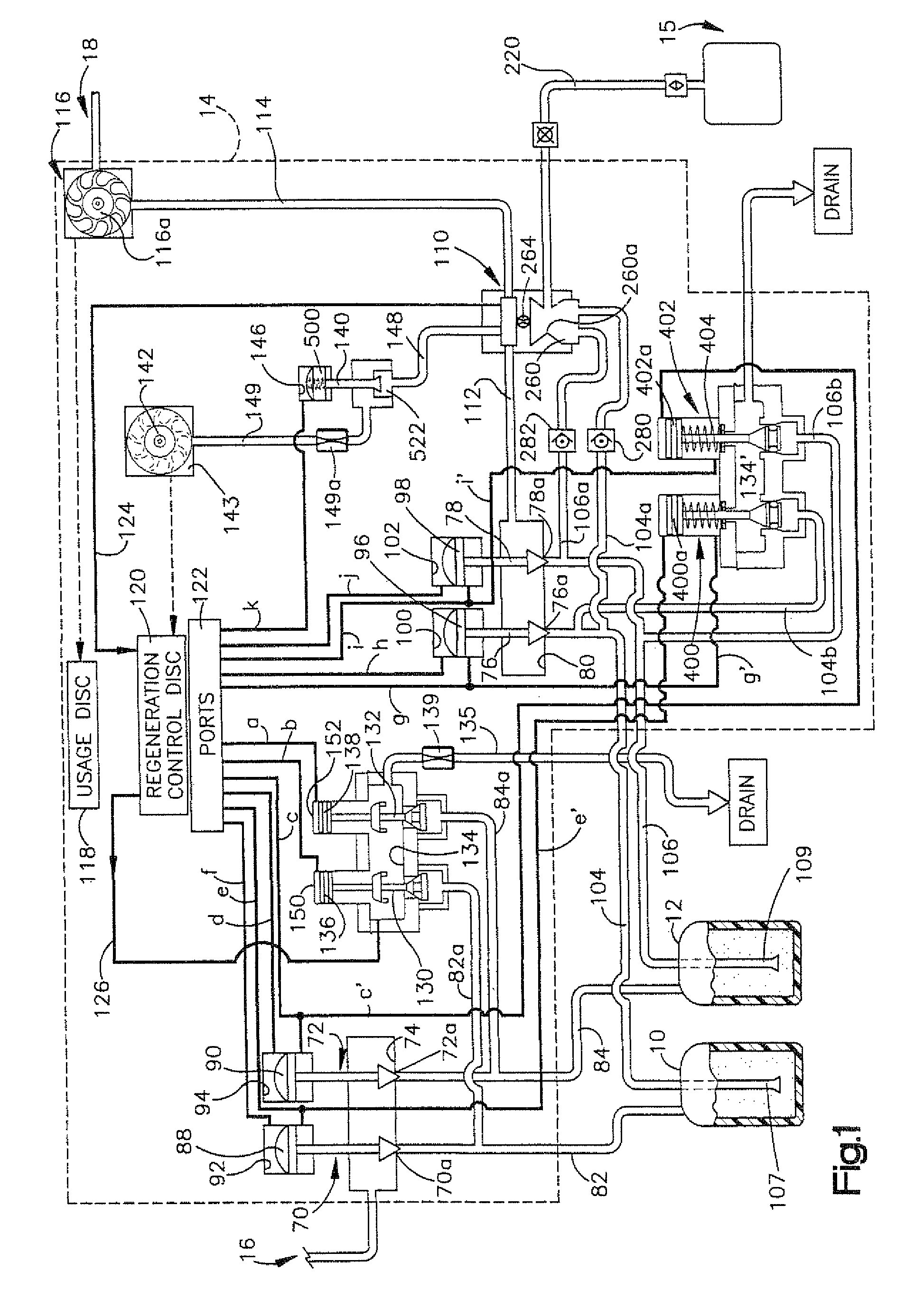
[0022]FIG. 1 schematically illustrates a water treatment system constructed in accordance with the preferred embodiment of the invention. The system includes a pair of resin tanks 10, 12 interconnected by a control valve module 14 that is similar to the control valves described in U.S. Pat. Nos. 4,298,025 and 3,891,552 which are hereby incorporated by reference. A source of regeneration solution indicated generally by the reference character 15 is connected to the valve 14.

[0023]The control valve assembly 14 controls the communication of a source of water to be treated, indicated generally by the reference character 16 with the treatment tanks 10, 12; the communication of the tanks with an outlet indicated by the reference character 18; and, the regeneration of an exhausted tank.

[0024]The valve assembly 14 includes a plurality of water pressure operated valves, the opening and closing of which are controlled by a fluid signal control system. Whether the tanks 10, 12 are on-line or o...


PUM

PropertyMeasurementUnit
distanceaaaaaaaaaa
pressureaaaaaaaaaa
frequencyaaaaaaaaaa

Abstract

A water treatment system including a pair of water treatment tanks, each tank defining a flow path extending from a tank inlet to a tank outlet and containing a water treatment material disposed along the flow path for treating water as it travels from the inlet to the outlet. A system controller controls which of the tanks is on-line and which of the tanks is off-line and controls the regeneration of an exhausted tank. A multi-stage, spring-loaded control valve assembly controls the communication of fluid to a regeneration control turbine and includes a piston head and a relatively movable seat-carrying stem. A spring urges the stem away from the piston head such that initial movement of the head compresses the spring but does not produce movement in the seat. Sufficient movement of the piston head produces movement in the seat, thereby causing the seat to open pressure.

Description

PRIORITY[0001]The present invention claims priority to U.S. Provisional Application Ser. No. 61 / 346,221, filed May 19, 2010, the entirety of which is incorporated herein by reference in its entirety.TECHNICAL FIELD[0002]The present invention relates generally to fluid treatment and in particular to an improved control system and control device for controlling a fluid treatment apparatus.BACKGROUND OF THE INVENTION[0003]U.S. Pat. No. 4,298,025, which is owned by the present assignee, discloses a control valve for use in water softeners having two resin tanks. One of the resin tanks is normally on-line while the other tank is regenerated and placed in a standby condition until the first tank requires regeneration. The disclosed control valve controls which of the tanks is on-line and controls the regeneration sequence of an exhausted tank.[0004]The quantity of water treated by a given tank, is monitored by a mechanism that includes a water usage turbine driven by water entering the on...

Claims


Application Information

Patent Timeline
Patent Type & Authority Patents(United States)
IPC IPC(8): C02F1/00C02F1/42B01J49/00B01D24/46
CPCC02F1/42B01J49/0095C02F1/008B01D24/4647C02F2201/005C02F2303/16B01J49/85
Inventor HANSEN, CHRISTOPHER L.HALEMBA, PETER
Owner KINETICO
Why Eureka
Try Eureka