Energy storage installation with open charging circuit for storing seasonally occurring excess electrical energy

a technology of energy storage and charging circuit, which is applied in the direction of indirect heat exchangers, machines/engines, lighting and heating apparatus, etc., can solve the problems of significant increase in the cost of heat exchangers, large heat exchanger surfaces, and high purchase costs of thermal energy stores, so as to improve efficiency and improve efficiency.

Active Publication Date: 2016-04-26
SIEMENS AG
View PDF22 Cites 2 Cited by
  • Summary
  • Abstract
  • Description
  • Claims
  • Application Information

AI Technical Summary

Benefits of technology

[0011]It is an object of the invention to specify an inexpensive energy storage installation for storing thermal energy on the basis of inexpensive storage materials, which energy storage installation exhibits improved efficiency. Here, it is sought in particular to avoid the disadvantages from the prior art. A further object of the invention is to specify a method by means of which thermal energy can be stored in inexpensive storage materials with improved efficiency.

Problems solved by technology

Thermal energy stores can thus be very expensive in terms of purchase costs simply owing to the structural size.
If the energy store is furthermore of complex design, or the actual energy storage medium is expensive in terms of production costs or cumbersome in terms of operation, the purchase and operating costs for a thermal energy store can quickly call into question the economic viability of the energy storage.
Owing to the often low thermal conductivity of the expensive storage materials, the heat exchanger surfaces must often be designed to be very large.
The large number and the length of heat exchanger pipes can in this case lead to a significant rise in costs of the heat exchanger, which costs can no longer be compensated by an inexpensive storage material.
The fluidized bed technique known in principle in the art has not hitherto been implemented on a scale that would be required for seasonal storage of excess renewable energy.
A direct exchange of heat furthermore entails relatively complicated handling of the solid matter, which is not economical for a large store.
A disadvantage here is however the additional cost outlay for the purchase and operation of an additional heat exchanger downstream of the expansion turbine, or upstream of the compressor, for heating the working gas to working temperature for the compressor.
During operation, this reduces the efficiency of the energy storage installation.
An expansion of the working gas in a single stage can have the effect that, owing to the intense cooling of the working gas to, for example, −100° C., the air moisture condenses and hereby damages the expansion turbine.
In particular, icing can cause permanent damage to turbine blades.
Disadvantages here, too, are however the increased cost outlay for the purchase of a multi-stage compressor and of a water separator.
Also, during operation, the efficiency of a plant of said type is reduced.

Method used


Image

  • Energy storage installation with open charging circuit for storing seasonally occurring excess electrical energy
  • Energy storage installation with open charging circuit for storing seasonally occurring excess electrical energy
  • Energy storage installation with open charging circuit for storing seasonally occurring excess electrical energy

Examples


Embodiment Construction

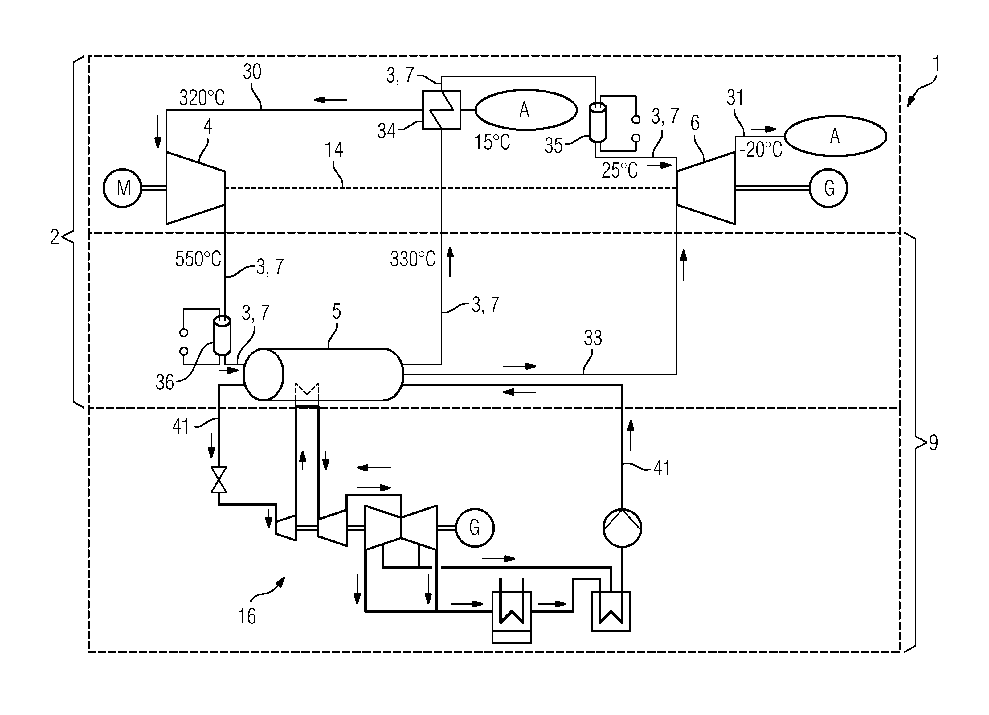
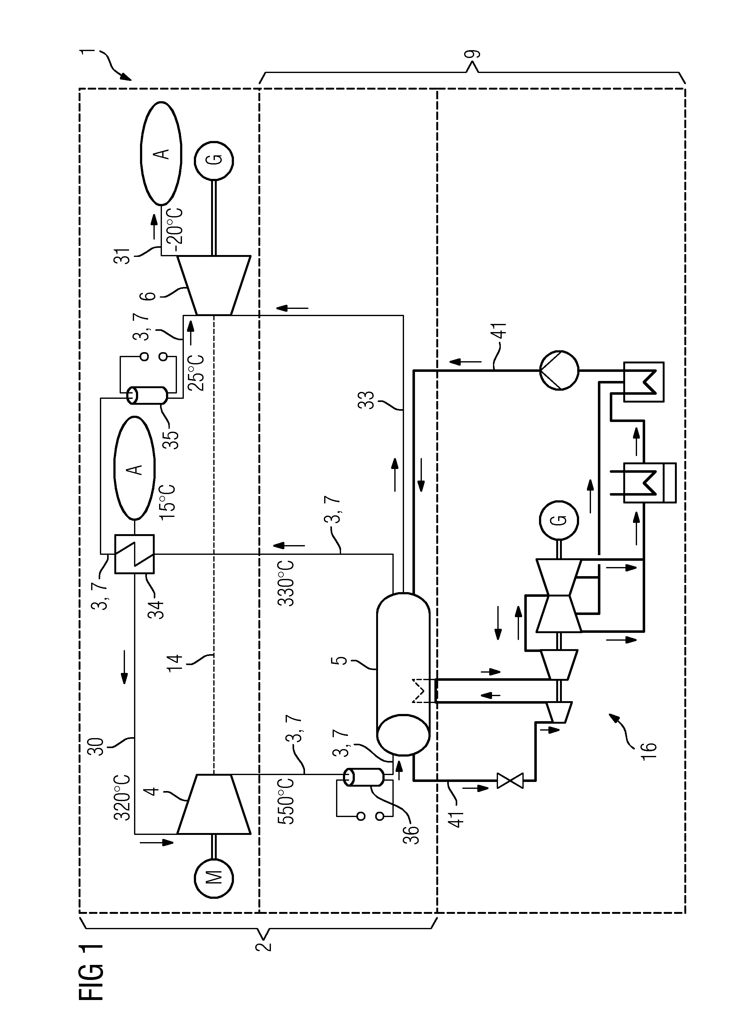
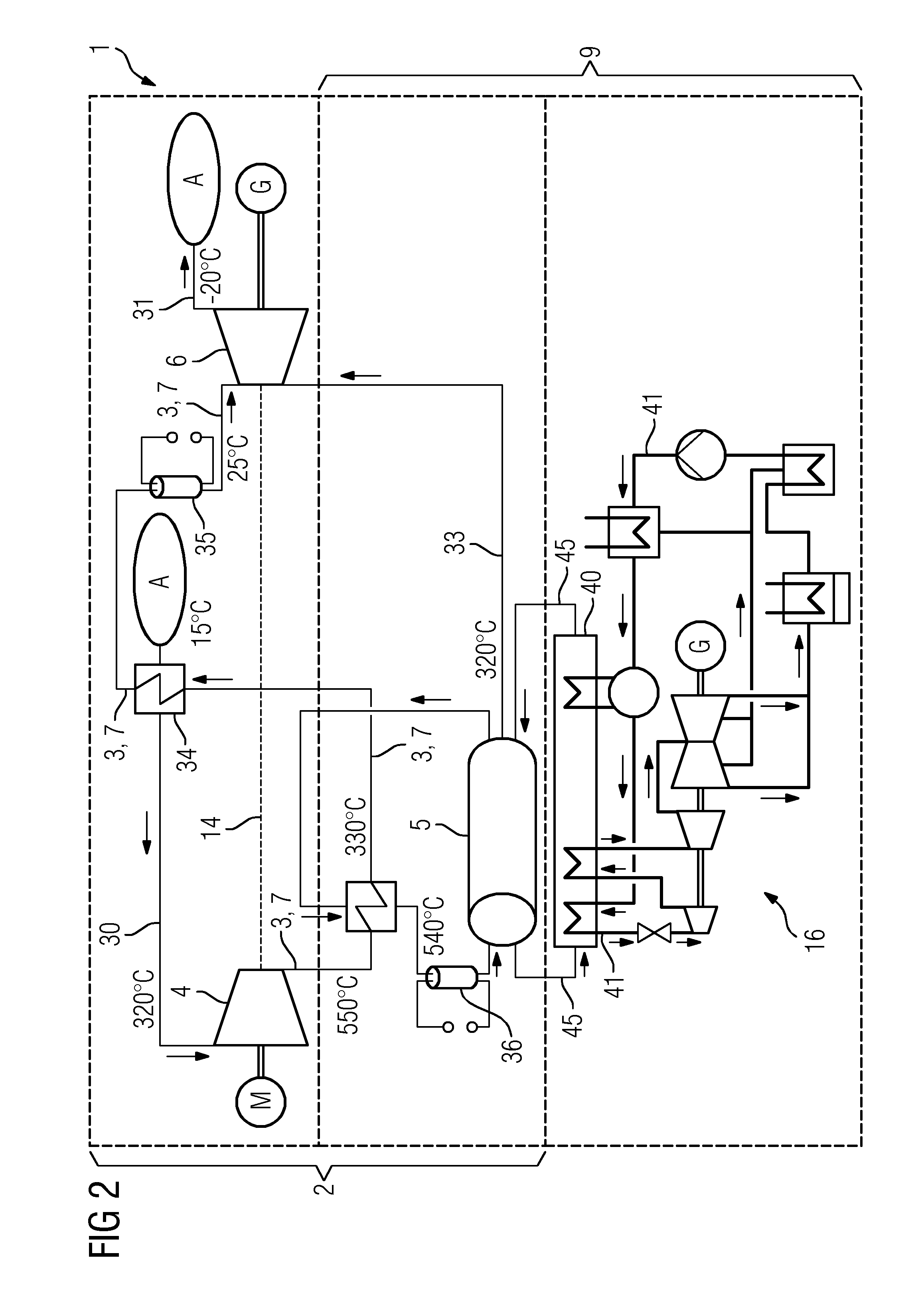
[0025]As shown in FIGS. 1-2, an energy storage installation 1 for storing thermal energy, having a charging circuit 2 for a working gas 3 is provided. The charging circuit has a compressor 4, a heat accumulator 5 and an expansion turbine 6. The compressor 4 and the expansion turbine 6 are arranged on a common shaft 14. The compressor 4 is connected at the outlet side to the inlet of the expansion turbine 6 via a first line 7 for the working gas 3, and the heat accumulator 5 is incorporated into the first line 7, and the compressor 4 is connected at the inlet side to a line 30 which is open to the atmosphere A, and the expansion turbine 6 is connected at the outlet side to a line 31 which is open to the atmosphere A, such that a circuit is formed which is open to the ambient air. The expansion turbine 6 is connected via a line 33 for a hot gas to the heat accumulator 5, such that the working gas 3 in the expansion turbine 6 can be heated by heat from the heat accumulator 5.

[0026]In e...


PUM


Abstract

An energy storage device for storing thermal energy, with a charging circuit for a working gas, is provided, having a compressor, heat accumulator and expansion turbine, the compressor and expansion turbine arranged on a common shaft, and the compressor connected on the outlet side to the inlet of the expansion turbine via a first line for the working gas, the heat accumulator wired into the first line, wherein the compressor is connected on the inlet side to a line, which is open to the atmosphere, and the expansion turbine is connected on the outlet side to a line, which is open to the atmosphere such that a circuit open to the ambient air is formed, wherein the expansion turbine is connected to the heat accumulator via a line for a hot gas such that the working gas in the expansion turbine can be heated by heat from the heat accumulator.

Description

CROSS REFERENCE TO RELATED APPLICATIONS[0001]This application is the US National Stage of International Application No. PCT / EP2012 / 072450 filed Nov. 13, 2012, and claims the benefit thereof. The International Application claims the benefit of German Application No. DE 102011088380.0 filed Dec. 13, 2011. All of the applications are incorporated by reference herein in their entirety.FIELD OF INVENTION[0002]The need for storing energy arises in particular from the progressively growing proportion of power plants operating in the renewable energies sector. Here, the aim of the energy storage is to make it possible to make the power plants with renewable energies usable in power transmission networks such that energy generated using renewables can also be made use of in a time-offset manner, in order thereby to save on fossil fuels and thus reduce CO2 emissions. The present invention relates to an energy storage installation with open charging circuit for storing seasonally occurring exc...

Claims


Application Information

Patent Timeline
Patent Type & Authority Patents(United States)
IPC IPC(8): F01K23/04F01K1/00F01K3/00F01K13/00F01K23/02F28D17/00
CPCF01K3/00F01K13/00F01K23/02F28D17/00
Inventor BRUNHUBER, CHRISTIANGRAEBER, CARSTENZIMMERMANN, GERHARD
Owner SIEMENS AG
Why Eureka
Try Eureka