Water seal at backpass economizer gas outlet

a backpass and gas outlet technology, applied in the direction of combustion treatment, manufacturing tools, lighting and heating apparatus, etc., can solve the problems of increased costs, increased system cost, and larger ‘footprint’

Active Publication Date: 2016-04-26
GENERAL ELECTRIC TECH GMBH
View PDF23 Cites 0 Cited by
  • Summary
  • Abstract
  • Description
  • Claims
  • Application Information

AI Technical Summary

Benefits of technology

[0047]Another advantage of the present invention is that it would reduce the need for the toggle section 13 reducing the ‘footprint’ size, requiring less real estate resulting in a cost saving.

Problems solved by technology

These larger toggle sections 13 require additional support structures and make the system more expensive.
Since the toggle sections are getting larger with larger boilers, they require extra room, which results in a larger ‘footprint’.
This larger footprint also incurs increased costs.

Method used


Image

  • Water seal at backpass economizer gas outlet
  • Water seal at backpass economizer gas outlet
  • Water seal at backpass economizer gas outlet

Examples


Embodiment Construction

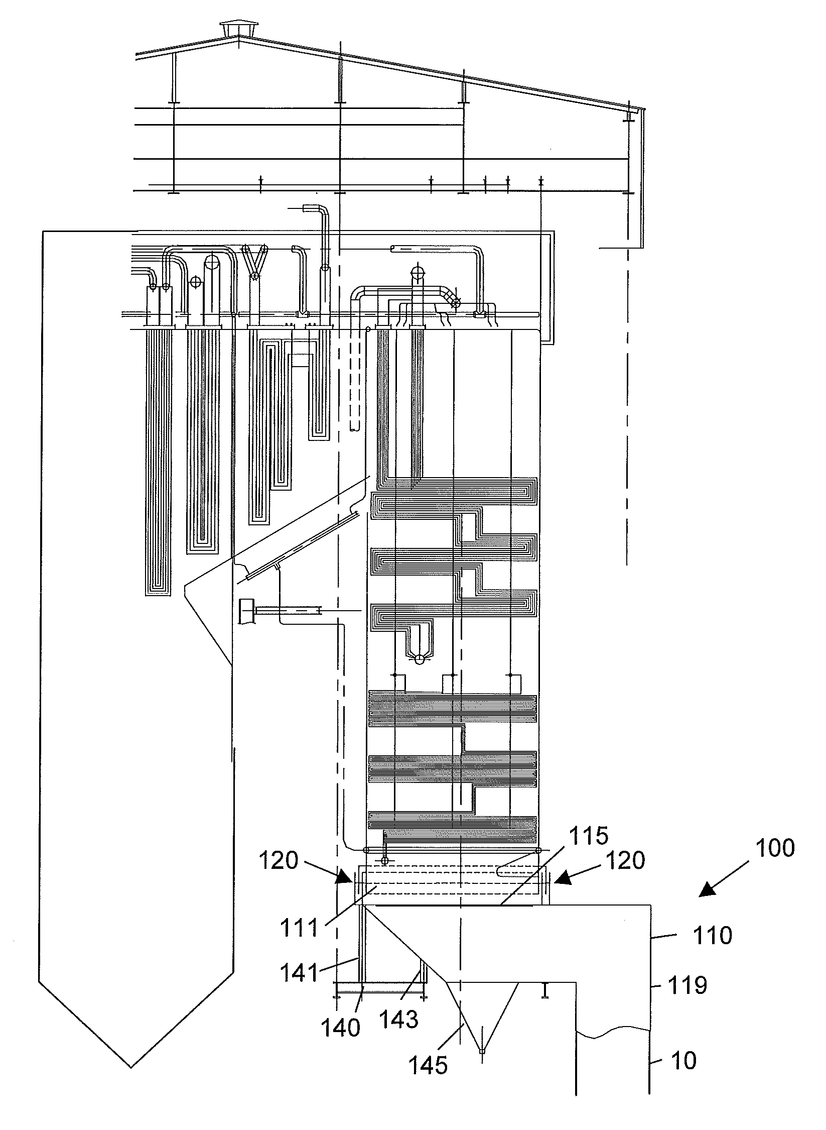
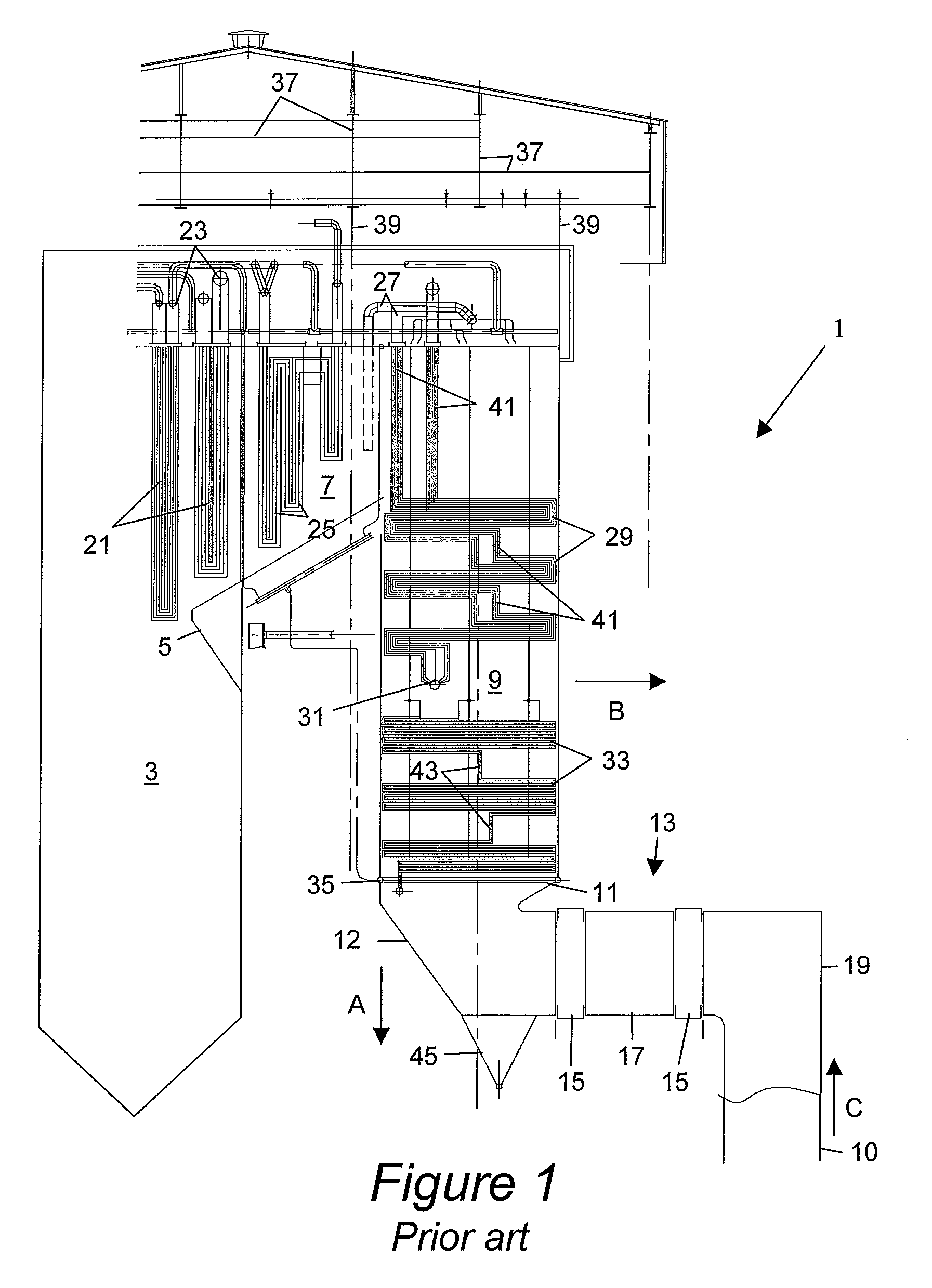
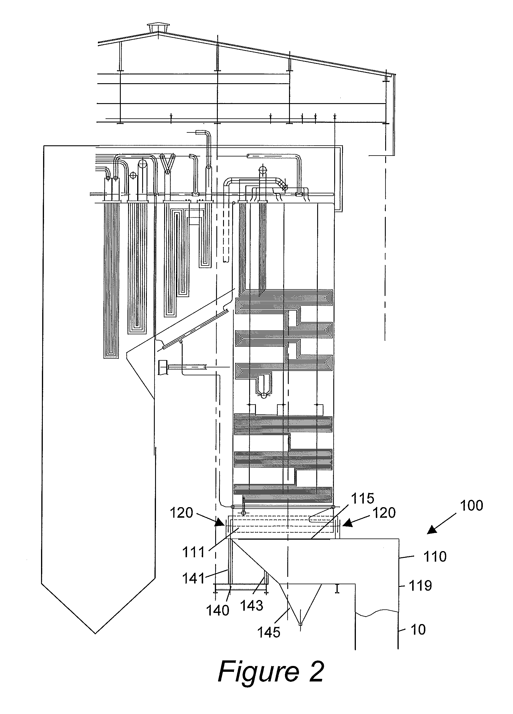
[0028]Referring now to FIG. 1, hot flue gases from the furnace 3 pass over super heaters 21 located in the top of the furnace and in a top pass 7. They receive steam and superheat the steam. The superheated steam is collected at the superheat headers 23. Similarly, steam enters the reheaters 25 in the top pass 7. There are also reheaters 29 and reheater headers 31 in a backpass 9. The backpass is lined with water tubes, but for clarity, are not shown here.

[0029]The lower backpass 9 has economizers 33 that receive feedwater, heat the feedwater. The heated feedwater is collected at a backpass lower ring header 35 and provide the heated feedwater to waterwalls of the furnace 3.

[0030]Typically, the top left of a furnace 3 is fixed to a stationary structure. When operating, the furnace 3 and flue gas ducts 1 expand to the right as indicated by arrow “B” and downward as indicated by arrow “C”.

[0031]An elbow duct 19 is connected to the air preheater duct 10 that is connected to the air pre...


PUM

PropertyMeasurementUnit
thermal expansionaaaaaaaaaa
widthaaaaaaaaaa
depthaaaaaaaaaa

Abstract

A compensations duct assembly [100] is described that provides a gas tight connection between a backpass [9] of a furnace [3] and an air preheater pipe [10] having one end fixed relative to a floor. The compensation duct assembly [100] has an air preheater opening [133] that is connected to an air preheater duct [10]. A liquid seal [120] is employed to compensate for the movement due to thermal expansion between the backpass [9] and the compensation duct assembly [100]. The liquid seal [120] provides a gas tight connection under various conditions of thermal expansion.

Description

BACKGROUND[0001]The present disclosure generally relates to a furnace flue gas connection that adjusts to movement caused by expansion.[0002]Various furnaces are used in industry to create power, incinerate waste or perform chemical processes. The flue gases are conveyed by interconnected flue gas ducts. These must maintain a gas-tight seal to prevent leakage of flue gases.[0003]FIG. 1 shows flue gas ducts 1 from a conventional furnace 3 (partially shown). The flue gas ducts 1 include a top pass 7 starting above a nose 5 of the furnace 3 connecting to a backpass 9.[0004]The backpass 9 extends downward to an economizer gas outlet duct 11. A backpass outlet manifold 12 attached to the economizer gas outlet duct 11. The backpass outlet manifold 12 includes an ash hopper 45 adapted to collect fly ash carried by the flue gases.[0005]Support structures 37 extend over the furnace and flue gas ducts 1. The furnace 3 and flue gas ducts 1 typically are hung from the support structures 37 with...

Claims


Application Information

Patent Timeline
Patent Type & Authority Patents(United States)
IPC IPC(8): F23J13/04F23J11/00F23L15/04
CPCF23J11/00F23L15/04F23J2213/204Y10T29/49826Y02E20/34
Inventor WINCZE, STEVEN P.
Owner GENERAL ELECTRIC TECH GMBH
Why Eureka
Try Eureka