
Periodic field differential mobility analyzer

a technology of differential mobility and analyzer, which is applied in the field of ion mobility spectrometry and ion analysis, can solve the problems of limiting the resolution of prior art dmas, unreliable type of instruments, and inability to select particles/ions according to their mobility, so as to increase the amount of electrical work and increase the resolution

Active Publication Date: 2016-04-26
ACAD SINIC
View PDF15 Cites 7 Cited by
  • Summary
  • Abstract
  • Description
  • Claims
  • Application Information

AI Technical Summary

Benefits of technology

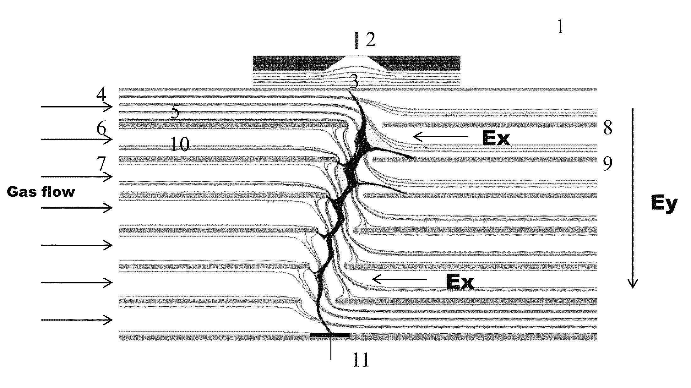
This patent describes a special kind of gas analyzer that can separate different gases with very high resolution. It uses a series of small analyzers that work simultaneously in a periodic pattern to increase the amount of electrical work done on the gas molecules, which makes them easier to separate. The overall pumping speed of the analyzer is reduced compared to a single analyzer running at a higher speed, but it achieves higher resolution for certain gases using a linearly increasing voltage and simultaneous selection / sweeping of the total voltage. The gas flow is recirculated back to each analyzer, which helps to achieve high resolution. This special analyzer gets its name from the way its electric fields change periodically, which is the key to its separation power.

Problems solved by technology

One disadvantage of TOF mobility analyzers is that the particles / ions are not easily selected according to their mobility.
Additional ion gates can be employed but aliasing of the mobility due to multiples of the period and the low resulting duty cycle make that type of instrument unreliable and inadequate for mobility selection.
These factors limit the resolution of prior art DMAs severely and the highest reported resolution of 60 required a Reynolds number approaching 100000.
These pumping requirements are impractical; therefore a new DMA design is needed.
Those factors may limit or even decrease the overall resolution.

Method used


Image

  • Periodic field differential mobility analyzer
  • Periodic field differential mobility analyzer
  • Periodic field differential mobility analyzer

Examples


example 1

[0083]A prototype PFDMA consisting of a pair of four 0.50 mm channels separated by 0.50 mm was constructed. The arrangement was similar to the schematic shown in FIG. 3, i.e. in an inline mode. The gas flow was produced using a common vacuum cleaner connected to a rheostat to set the velocity, drawn in from the surrounding laboratory air (unfiltered). The ion source consisted of a thin tungsten wire biased to 2 kV relative to two tungsten wire counter electrodes. Detection of ions was made by a sensitive current to voltage converter. Spectra were acquired by manually stepping the total voltage and recording the average ion current at each voltage step.

[0084]Referring now to FIG. 10a, a spectrum of voltage versus ion intensity (inverse ion mobility versus ion intensity) is shown for background air ions in negative mode. One peak is present in the spectrum, most probably O− or O2− or a small reactant product of these species; because the mobility is high (a low voltage is required to ...

example 2

[0089]A prototype PFDMA comprising a pair of six 0.50 mm channels separated by 0.50 mm was constructed. The arrangement was similar to the schematic shown in FIG. 3, i.e. in an inline mode. The gas flow was produced using a common vacuum cleaner connected to a rheostat to set the velocity, drawn in from the surrounding unfiltered laboratory air. The ion source consisted of a thin tungsten wire biased to 2 kV relative to two tungsten wire counter electrodes. Detection of ions was made by a sensitive current to voltage converter. Spectra were acquired by using a computer to simultaneously step the voltages of individual programmable high voltage power supplies connected to each electrode and recording the average ion current at each voltage step using an ADC board.

[0090]Referring now to FIG. 12a, an overlay spectrum of voltage versus ion intensity (inverse ion mobility versus ion intensity) is shown for background air ions (most probably clusters ions of H2O) and product ions of aceto...


PUM

PropertyMeasurementUnit
voltage dropaaaaaaaaaa
flow rateaaaaaaaaaa
inlet flow ratesaaaaaaaaaa

Abstract

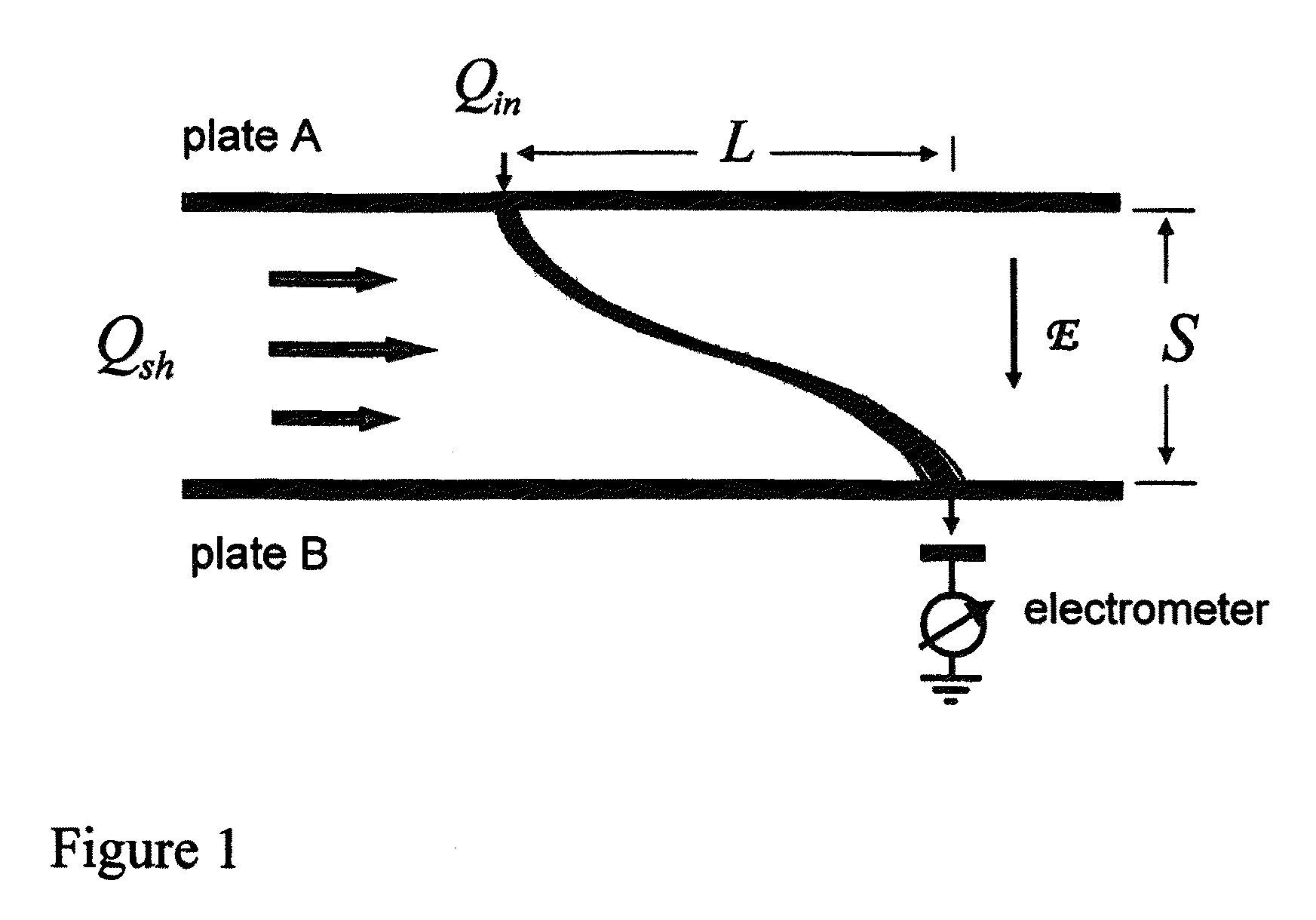
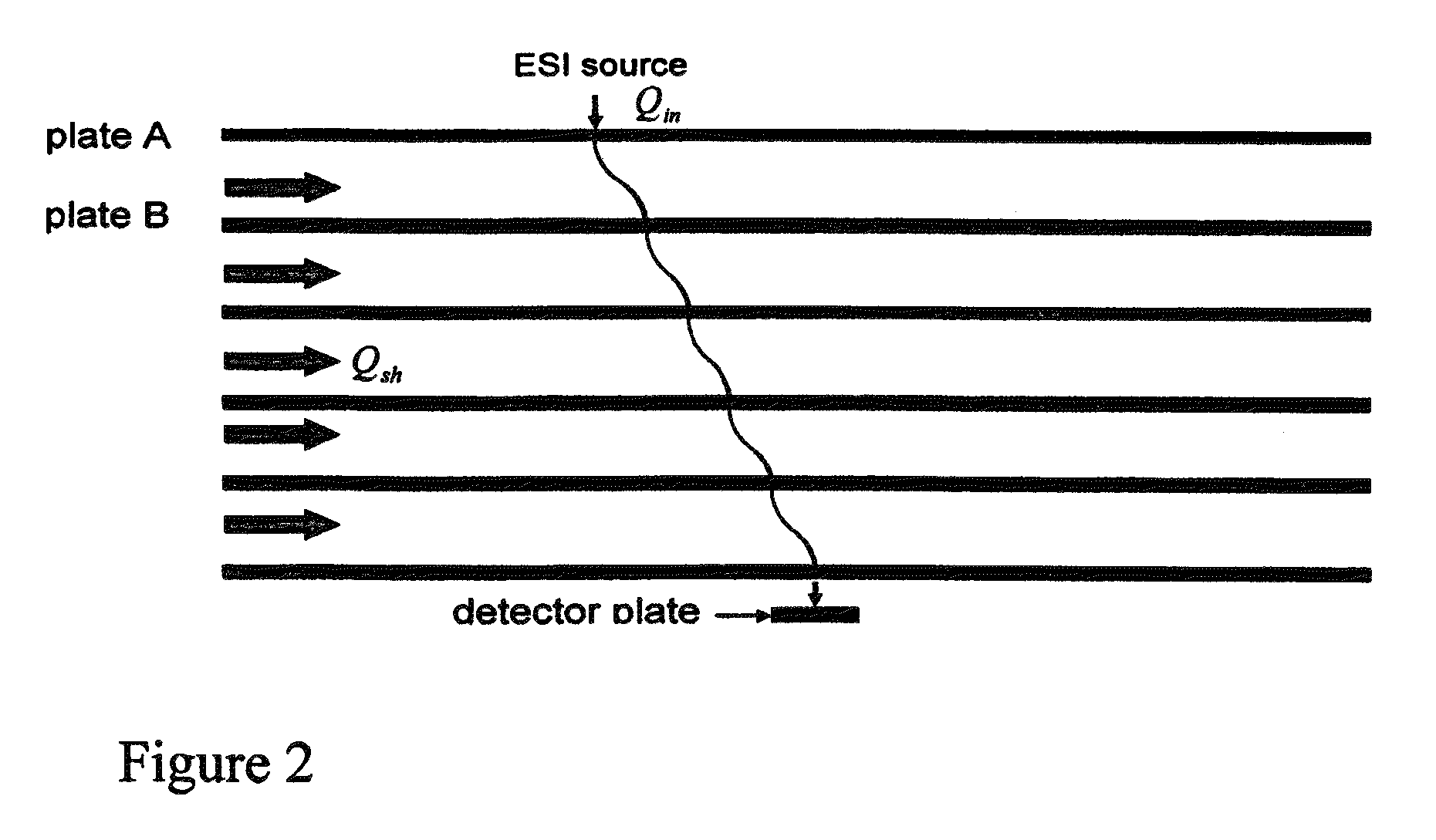
A periodic field differential mobility analyzer apparatus for separating and identifying ionic analytes employs a series of elongated parallel channels, a pump, a first voltage providing an electric field Ex in a direction opposing the gas flow, a second voltage providing an electric field Ey in a direction perpendicular to the gas flow, an ion source, and a detector. The periodic field differential mobility analyzer provides high resolution and sensitivity.

Description

TECHNICAL FIELD OF THE INVENTION[0001]This invention relates to the fields of ion mobility spectrometry and ion analysis. In particular, this application relates to methods for separation and identification of ions, molecules and particles. More particularly, this application relates to an apparatus and methods for separation and analysis of ions by differential mobility with a periodic field.BACKGROUND OF THE INVENTION[0002]Ion Mobility Spectrometry (IMS) is a technique that separates ions in terms of their mobility with reference to a drift / buffer gas. The analysis is based on measuring the velocity which gaseous ions attain while drifting a defined distance through the buffer gas. Prior art mobility techniques are known as “time-of-flight” separation techniques if based on time or as “differential” separation techniques if ion detection is based on position. Drift-tube mobility analyzers operate by recording the time-of-flight of ion packets separated by their mobility in a backg...

Claims


Application Information

Patent Timeline
Patent Type & Authority Patents(United States)
IPC IPC(8): H01J49/28G01N27/62H01J49/26H01J49/22H01J49/00
CPCH01J49/26G01N27/624H01J49/0031H01J49/22
Inventor GILLIG, KENT J.CHEN, CHUNG-HSUAN
Owner ACAD SINIC
Learn More