
Method for measuring opening and closing delay time of elevator brake

a technology of elevator brake and delay time, which is applied in the direction of elevators, transportation and packaging, etc., can solve the problems of moment to be applied to the shaft, disadvantageous increase in wear of the brake lining, etc., and achieve the effect of stable brake operation

Active Publication Date: 2016-05-17
LSIS CO LTD
View PDF9 Cites 0 Cited by
  • Summary
  • Abstract
  • Description
  • Claims
  • Application Information

AI Technical Summary

Benefits of technology

The present invention provides a system and method for measuring the opening and closing delay time of elevator brakes. This prevents the roll-back phenomenon when the brakes are opened and closed at the wrong time. The system automatically computes the delay time and sets it to prevent the roll-back phenomenon. This also prevents wear and tear of brake lining and ensures stable operation of brakes.

Problems solved by technology

A load imbalance between an elevator car and a balance (counter) weight is continuously generated in the rope type elevator due to loaded weight of persons and cargos in an elevator car, and a heavier force is applied to a direction on a contact surface between a hoist and a wire rope as much as the imbalance, thereby resulting in a moment to be applied to a shaft of the hoist.
At this time, the time of the brake being opened and closed is set to be a bit delayed over a time of controlling a motor, where a roll-back phenomenon of an elevator being instantly leaned to a weightier side between an elevator car and a balance weight may be generated, when a brake delay opening and closing time is set at an excessively smaller value.
Conversely, although the roll-back phenomenon of the elevator may be prevented when a brake delay opening and closing time is set at an excessively greater value, wear of brake lining disadvantageously increases because the brake shoe is opened after the motor starts to rotate in a state of the brake shoe holding the brake drum.

Method used


Image

  • Method for measuring opening and closing delay time of elevator brake
  • Method for measuring opening and closing delay time of elevator brake
  • Method for measuring opening and closing delay time of elevator brake

Examples


Embodiment Construction

[0027]Now, exemplary embodiments of the present disclosure will be described in detail with reference to the accompanying drawings, so that one of ordinary skill in the art can easily implement the present disclosure upon examination of the figures and detailed description.

[0028]Accordingly, detailed descriptions of well-known functions, configurations or constructions are omitted for brevity and clarity so as not to obscure the description of the present disclosure with unnecessary detail. Thus, the present disclosure is not limited to the exemplary embodiments which will be described below, but may be implemented in other forms. In the drawings, the width, length, thickness, etc. of components may be exaggerated or reduced for the sake of convenience. Furthermore, the meaning of specific terms or words used in the specification and claims should not be limited to the literal or commonly employed sense, but should be construed or may be different in accordance with the intention of...


PUM


Abstract

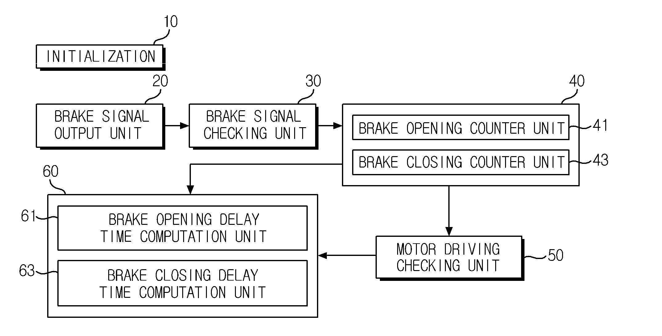
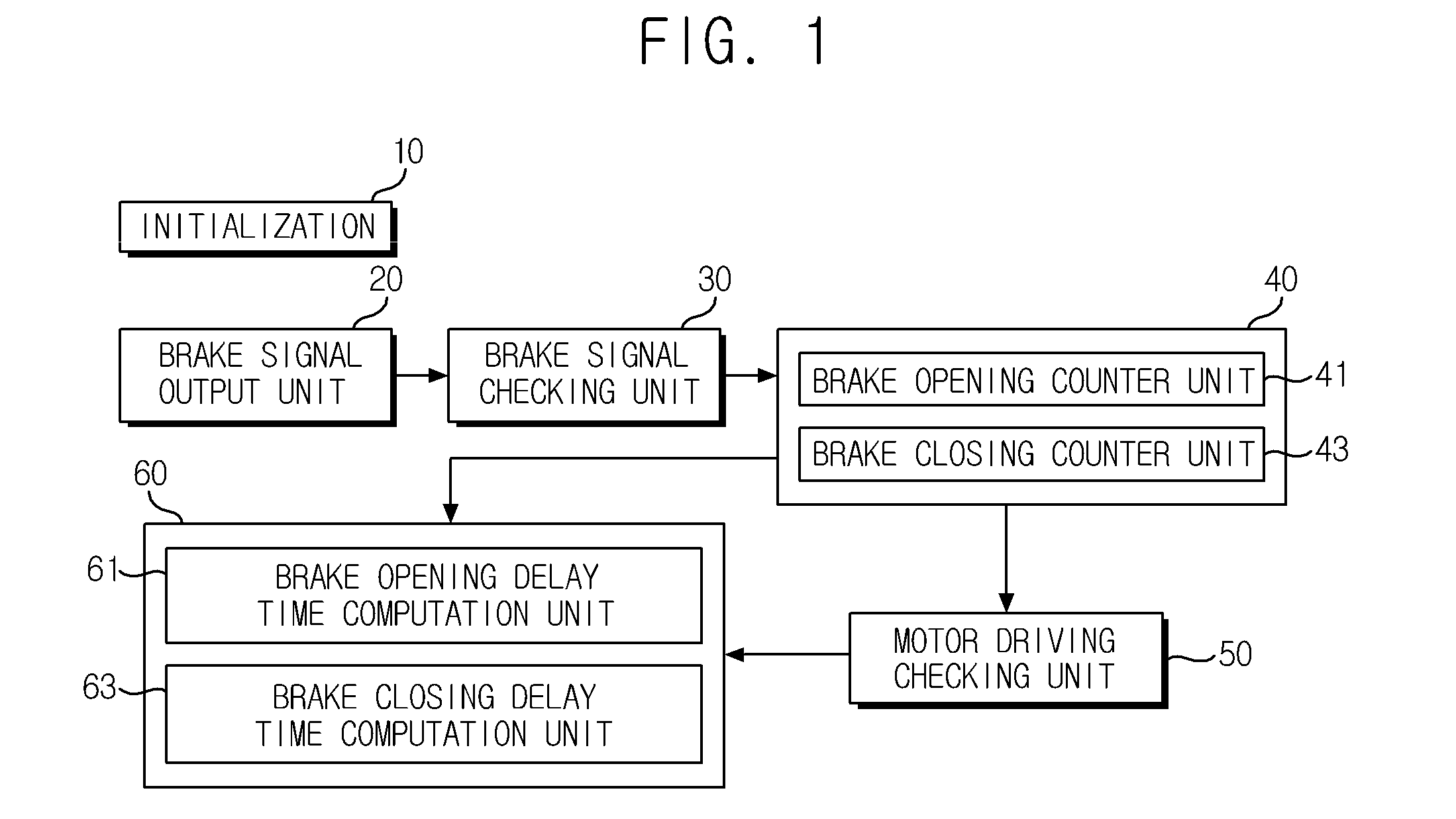
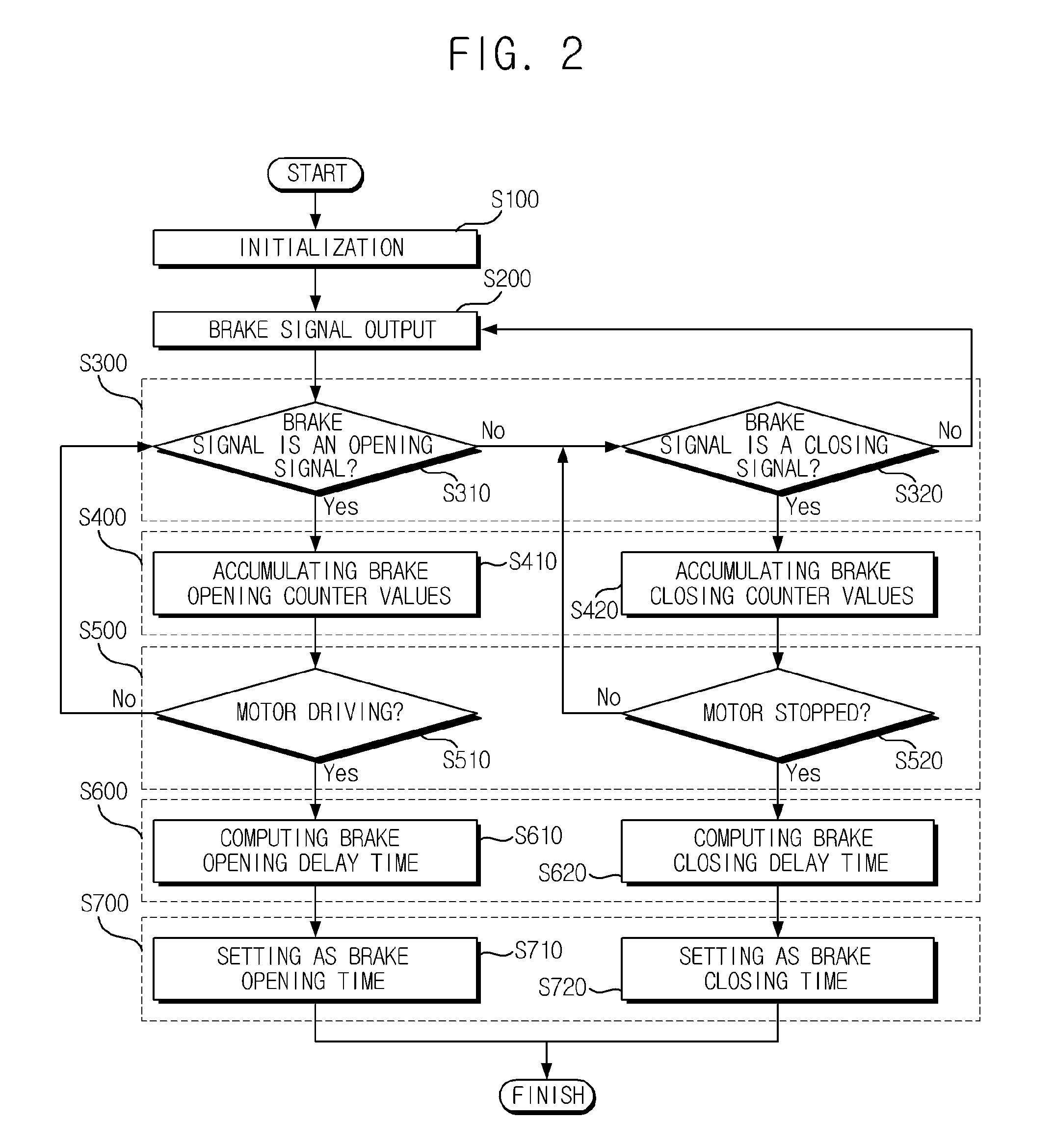
Disclosed is a method for measuring opening and closing delay time of elevator brake, the method including outputting, by a brake signal output unit, a brake signal, receiving, by a brake signal checking unit, the brake signal and determining whether the brake signal is an opening signal or a closing signal to output an opening / closing determination signal, receiving, by a brake counter unit, the opening / closing determination signal, and starting a count for measuring a brake opening time or a brake closing time to accumulate and output counted value, determining, by a motor drive checking unit, whether a motor configured to drive an elevator is driven upon receipt of the counted values and outputting a drive determination signal, and receiving, by a brake opening / closing delay computation unit, the drive determination signal and the counted value to compute a brake opening / closing delay time.

Description

CROSS-REFERENCE TO RELATED APPLICATIONS[0001]Pursuant to 35 U.S.C. §119(a), this application claims the benefit of earlier filing date and right of priority to Korean Patent Application No.10-2013-0102911, filed on Aug. 29, 2013, the contents of which are all hereby incorporated by reference herein in its entirety.BACKGROUND OF THE DISCLOSURE[0002]1. Field of Endeavor[0003]Exemplary embodiments of the present disclosure relate to a method for measuring opening and closing delay time of elevator brake, and more particularly to a method for measuring opening and closing delay time of elevator brake configured to prevent a roll-back phenomenon of an elevator by automatically calculating elevator brake opening / closing delay time for setting elevator brake opening / closing time, and to allow a stable performance of brake operation.[0004]2. Discussion of the Related Art[0005]Elevators installed inside and / or outside of a building for lifting persons or cargos are mostly of hoist winding ty...

Claims


Application Information

Patent Timeline
Patent Type & Authority Patents(United States)
IPC IPC(8): B66B5/00B66B1/32
CPCB66B1/32B66B5/0037B66B1/3415B66B2201/242B66B1/3407
Inventor CHI, MIN HUN
Owner LSIS CO LTD
Learn More