Method for calibrating a digital optical instrument and digital optical instrument

a digital optical instrument and digital optical technology, applied in the field of optical instrument calibration, can solve the problems of most complicated design of plan apochromats, prone to error in image representation, and inability to accurately reflect images

Active Publication Date: 2016-05-17
CARL ZEISS MICROSCOPY GMBH
View PDF11 Cites 8 Cited by
  • Summary
  • Abstract
  • Description
  • Claims
  • Application Information

AI Technical Summary

Benefits of technology

[0014]The invention is based on the object of specifying a method for calibrating a digital microscope or a different optical system, which method in particular simplifies the manufacturing process of modular systems and enables a quick and simple calibration in respect of different aberrations when an objective is changed. Furthermore, the provision of a digital microscope with such a calibration logic is sought after.
[0030]A first calibration when assembling the optical system is very simple on the basis of the calibration on a reference object in each case.

Problems solved by technology

Production tolerances of the optical components, that is to say of the zoom systems and of the objectives, cause aberrations in the image representation, whether this be the actual magnification of an objective or of the specific zoom setting, a deviation of the image steadiness from the center, image distortions, color aberrations or other aberrations.
Imaging by lenses is always error-prone to a greater or lesser extent.
Of all objectives, the plan apochromats have the most complicated design.
Additionally, the usually occurring red and blue color fringes are suppressed in these objectives by the very complicated design.
These objectives are very expensive and are primarily used in color micro-photography with the highest demands.

Method used


Image

  • Method for calibrating a digital optical instrument and digital optical instrument
  • Method for calibrating a digital optical instrument and digital optical instrument
  • Method for calibrating a digital optical instrument and digital optical instrument

Examples


Embodiment Construction

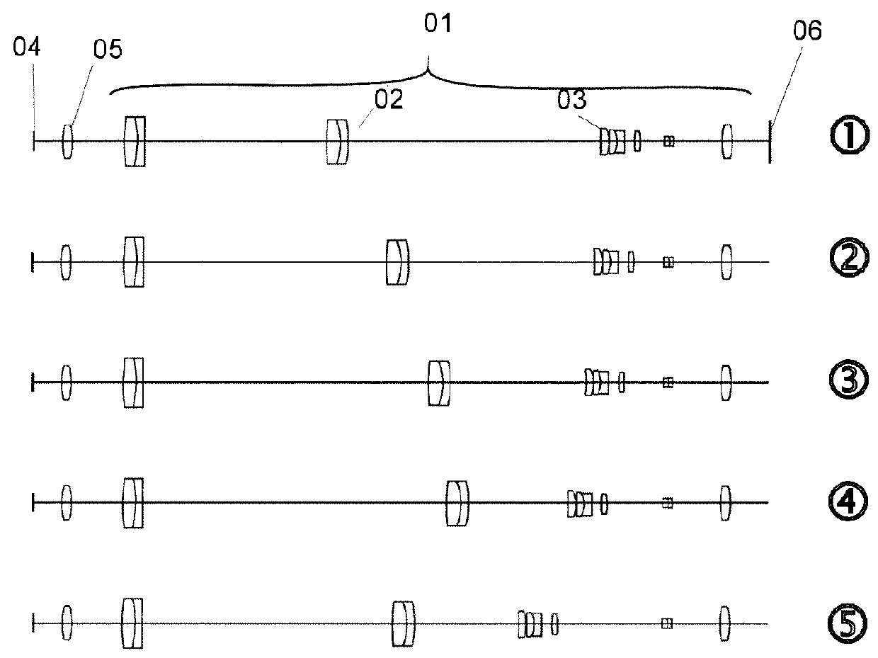
[0042]FIG. 1 shows a schematic illustration of a zoom system 01 with two movable lens groups and one fixed lens group in various positions. A first movable lens group 02 initially serves for setting the focus while a second lens group 03 sets the magnification factor β. The lens groups 02, 03 can be displaced in extremely small steps by means of stepper motors (not depicted here). During operation of the digital microscope. there are fixed zoom tables, which store the respective motor positions of the two lens groups. Both motors are preferably put into motion simultaneously in order to arrive at a desired zoom setting particularly quickly. In a manner known per se, the zoom system 01 is arranged in the beam path from an object 04 to an image sensor 06 via an objective 05 and the zoom system 01.

[0043]In order to establish calibration data DZ of the zoom system 01 with a reference objective, the objective (e.g. a 5×0.3 objective with installed object plane) is, in a preferred embodim...


PUM


Abstract

The invention relates to a method for calibrating an optical instrument which comprises at least a motorized zoom system, an objective, an image sensor and an image processing unit. The method comprises the following steps: establishing calibration data DZRef of the zoom system with a reference objective and storing these in an internal memory of the zoom system; establishing calibration data DORef of the objective with a reference zoom system and storing these in an internal memory of the objective; reading the internal memories of the zoom system and of the objective and applying a digital-optical correction of an image acquired by an image sensor with the calibration data DZRef and DORef. The invention moreover relates to an optical instrument, in particular a digital microscope, to which the calibration method according to the invention can be applied.

Description

TECHNICAL FIELD[0001]The invention relates to a method for calibrating an optical instrument, in particular for digital microscopes and modular optical systems, which comprise independent zoom systems and, optionally, objectives. Additionally, the invention relates to a digital microscope or a digital optical system, in which such a method is implemented or which is suitable for the application of a method according to the invention.SUMMARY OF THE INVENTION[0002]Production tolerances of the optical components, that is to say of the zoom systems and of the objectives, cause aberrations in the image representation, whether this be the actual magnification of an objective or of the specific zoom setting, a deviation of the image steadiness from the center, image distortions, color aberrations or other aberrations.[0003]Aberration means that the various light rays emanating from the object point are not all focused on an image point. The most important aberrations are spherical aberrati...

Claims


Application Information

Patent Timeline
Patent Type & Authority Patents(United States)
IPC IPC(8): H04N5/357H04N5/232G02B21/36H04N17/00
CPCH04N5/23296H04N5/357G02B21/365H04N5/3572H04N17/002H04N5/00H04N23/69H04N25/60H04N25/61
Inventor WINTEROT, JOHANNESMILDE, THOMASFUNCK, MAXJABBOUR, TOUFICKNOBLICH, JOHANNES
Owner CARL ZEISS MICROSCOPY GMBH
Why Eureka
Try Eureka