Steering system with magnetic torque overlay

a technology of magnetic torque overlay and steering system, which is applied in the direction of power steering, fluid steering, vehicle components, etc., can solve the problems of insufficient output of electric power steering system or hydraulic rack-and-pinion steering system to perform park-assist or may not, and the size of the magnetic actuator may need to be increased

Active Publication Date: 2016-05-24
STEERING SOLUTIONS IP HLDG
View PDF12 Cites 9 Cited by
  • Summary
  • Abstract
  • Description
  • Claims
  • Application Information

AI Technical Summary

Benefits of technology

[0009]By varying the size of the magnetic actuator, the steering system enables park-assist along with lane-keeping, lead-and-pull compensation, driver-alert, active return-to-center, active dampening, and stability-control assist. Furthermore, the steering system is hydraulically assisted for power-steering, has sufficient output, and can be packaged in the vehicle. In addition, the magnetic actuator can be very compact and smaller in size than current electromagnetic actuators. Moreover, the magnetic actuator can be manufactured fairly easily, which, in combination with the smaller size, makes the magnetic actuator less expensive to manufacture.

Problems solved by technology

This state can be caused by vehicle, road, and / or weather conditions (such as a crosswind that requires a force for the steering system to overcome) or an imbalance in the steering system (such as if a valve is balanced in a “null” position and a torsion bar is on center, but a valve spool is creating pressure in the steering system).
However, some systems may not have any capability to perform additional “performance” features or functions such as park-assist, lane-keeping, lead-and-pull compensation, driver-alert, active return-to-center, active dampening, or stability-control assist.
Also, an electric power-steering system or hydraulic rack-and-pinion steering system may not have sufficient output to perform a park-assist or may not be able to be packaged in the vehicle.
However, to perform park-assist, size of the magnetic actuator may need to be increased such that a sufficient amount of torque is produced in the steering system to generate full hydraulic assist.
Therefore, the magnetic actuator may be difficult to package in the vehicle.

Method used


Image

  • Steering system with magnetic torque overlay
  • Steering system with magnetic torque overlay
  • Steering system with magnetic torque overlay

Examples


Embodiment Construction

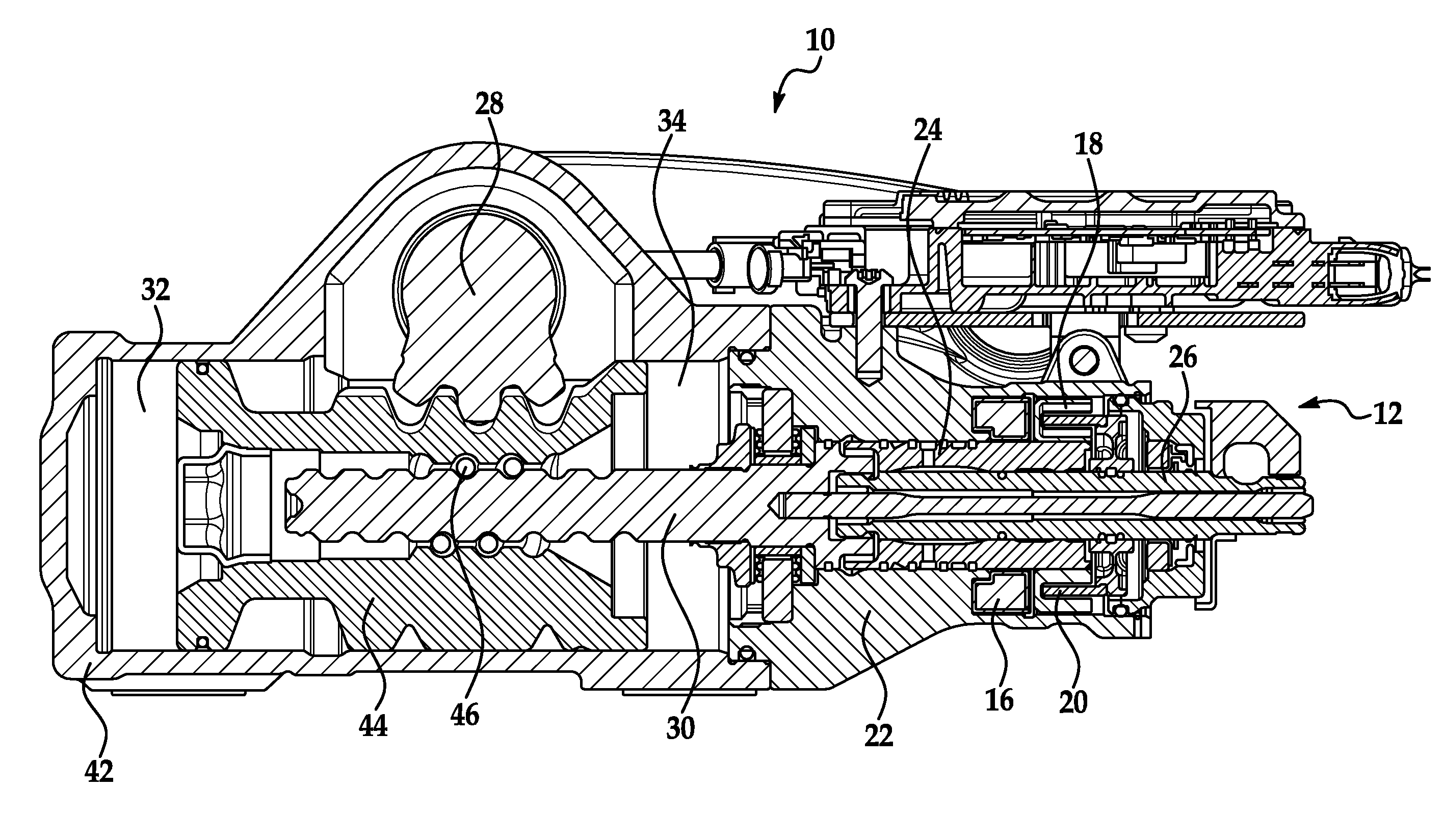
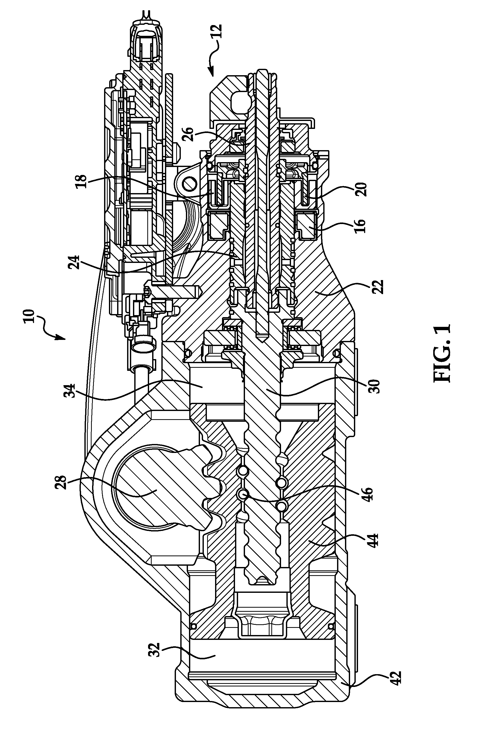
[0014]A power-steering system of a motor vehicle is designed to provide appropriate hydraulic or electrical steering assist to allow a driver of the vehicle to complete a turn thereof. The driver applies a steering input through a manual steering wheel (otherwise known as a hand wheel) that is rotationally connected to a first shaft, which is is rotationally coupled to a second shaft that is, in turn, connected to a steering mechanism. The first and second shafts are torque transmittingly coupled to each other by a compliant member, such as a torsion bar. The torsion bar allows the first shaft to rotate with respect to the second shaft by a predetermined number of degrees (e.g., + / −12 degrees). Mechanical stops prevent further rotation. An amount of the steering assist applied to the steering mechanism is determined as a function of degree of torsional strain or movement in the torsion bar.

[0015]A non-limiting exemplary power-steering system is a hydraulic “variable effort” steering...


PUM


Abstract

A steering system with magnetic torque overlay of a vehicle is provided. The system comprises a hydraulic valve and differential-pressure transducer that monitors pressure created by the valve due to torque exerted by a driver of the vehicle in various directions on a steering wheel thereof. The transducer is fastened to a recirculating ball steering gear. A magnetic actuator generates an output of torque required from the steering gear for a maneuver of the steering wheel and applies the torque to the valve independently of input by the driver. A permanent magnet is located proximate the actuator. A control module calculates an appropriate amount of electric current and sends it to the actuator to generate the output torque. The torque is added to or subtracted from the system in any of the directions independently of the driver input by the pressure-monitoring and inputs from the vehicle into the control module.

Description

CROSS-REFERENCE TO RELATED APPLICATION[0001]This application is based upon and claims benefit of the filing date of U.S. Patent Application 61 / 893,554 filed on Oct. 21, 2013 and entitled “Steering System with Magnetic Torque Overlay,” which is incorporated herein by reference in its entirety.FIELD OF INVENTION[0002]The invention relates to a steering system of a vehicle and, in particular, such a system having variable-effort steering.BACKGROUND OF INVENTION[0003]In a motor vehicle, a “pulling” state, for example, can occur such that a driver of the vehicle has to input torque into a steering system thereof to maintain a straight path. This state can be caused by vehicle, road, and / or weather conditions (such as a crosswind that requires a force for the steering system to overcome) or an imbalance in the steering system (such as if a valve is balanced in a “null” position and a torsion bar is on center, but a valve spool is creating pressure in the steering system). Either way, an i...

Claims


Application Information

Patent Timeline
Patent Type & Authority Patents(United States)
IPC IPC(8): B62D5/065B62D5/09B62D5/083
CPCB62D5/065B62D5/0835B62D5/09B62D5/24
Inventor DUTSKY, JASON A.POWELL, JEFFREY M.MARTIN, BRENDA L.BIRSCHING, JOEL E.
Owner STEERING SOLUTIONS IP HLDG
Why Eureka
Try Eureka