
Dynamic thermal budget allocation for memory array

a memory array and dynamic technology, applied in the direction of memory allocation/allocation/relocation, instruments, power supply for data processing, etc., can solve the problems of thermal budget waste, high load, and may reach the thermal budget limit, so as to reduce the throttling of the particular memory group and increase the number of credits

Active Publication Date: 2016-05-24
SAMSUNG ELECTRONICS CO LTD
View PDF20 Cites 3 Cited by
  • Summary
  • Abstract
  • Description
  • Claims
  • Application Information

AI Technical Summary

Benefits of technology

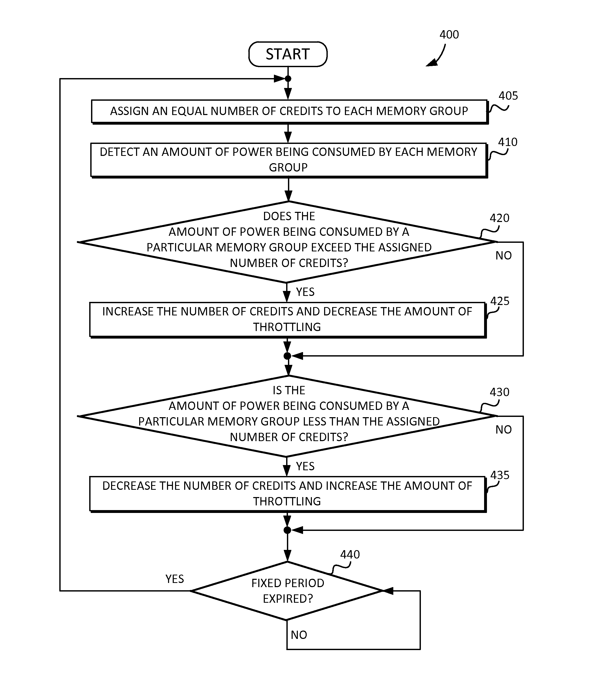
The patent describes a method for managing the temperature of a computer chip with memory. The method involves assigning a certain number of credits to each type of memory in the chip and measuring the amount of power or current consumed by each type of memory. If the amount of power or current exceeds the assigned number of credits, the chip will assign more credits to the memory and reduce its activity. If the amount of power or current is below the assigned number of credits, the chip will assign fewer credits to the memory and increase its activity. This allows for efficient management of the chip's temperature and improved performance.

Problems solved by technology

But for most cases, the load on each memory group is not evenly distributed.
In other words, one memory group might have a high load and may reach the thermal budget limit for its fraction of the total thermal budget, while another memory group in the same system with low load might have extra unused thermal budget.
As a result, thermal budget is wasted and the dynamic performance of the system is limited because of the unused thermal budget margins.

Method used


Image

  • Dynamic thermal budget allocation for memory array
  • Dynamic thermal budget allocation for memory array
  • Dynamic thermal budget allocation for memory array

Examples


Embodiment Construction

[0025]Reference will now be made in detail to embodiments of the inventive concept, examples of which are illustrated in the accompanying drawings. In the following detailed description, numerous specific details are set forth to enable a thorough understanding of the inventive concept. It should be understood, however, that persons having ordinary skill in the art may practice the inventive concept without these specific details. In other instances, well-known methods, procedures, components, circuits, and networks have not been described in detail so as not to unnecessarily obscure aspects of the embodiments.

[0026]It will be understood that, although the terms first, second, etc. may be used herein to describe various elements, these elements should not be limited by these terms. These terms are only used to distinguish one element from another. For example, a first thermal budget could be termed a second thermal budget, and, similarly, a second thermal budget could be termed a fi...


PUM


Abstract

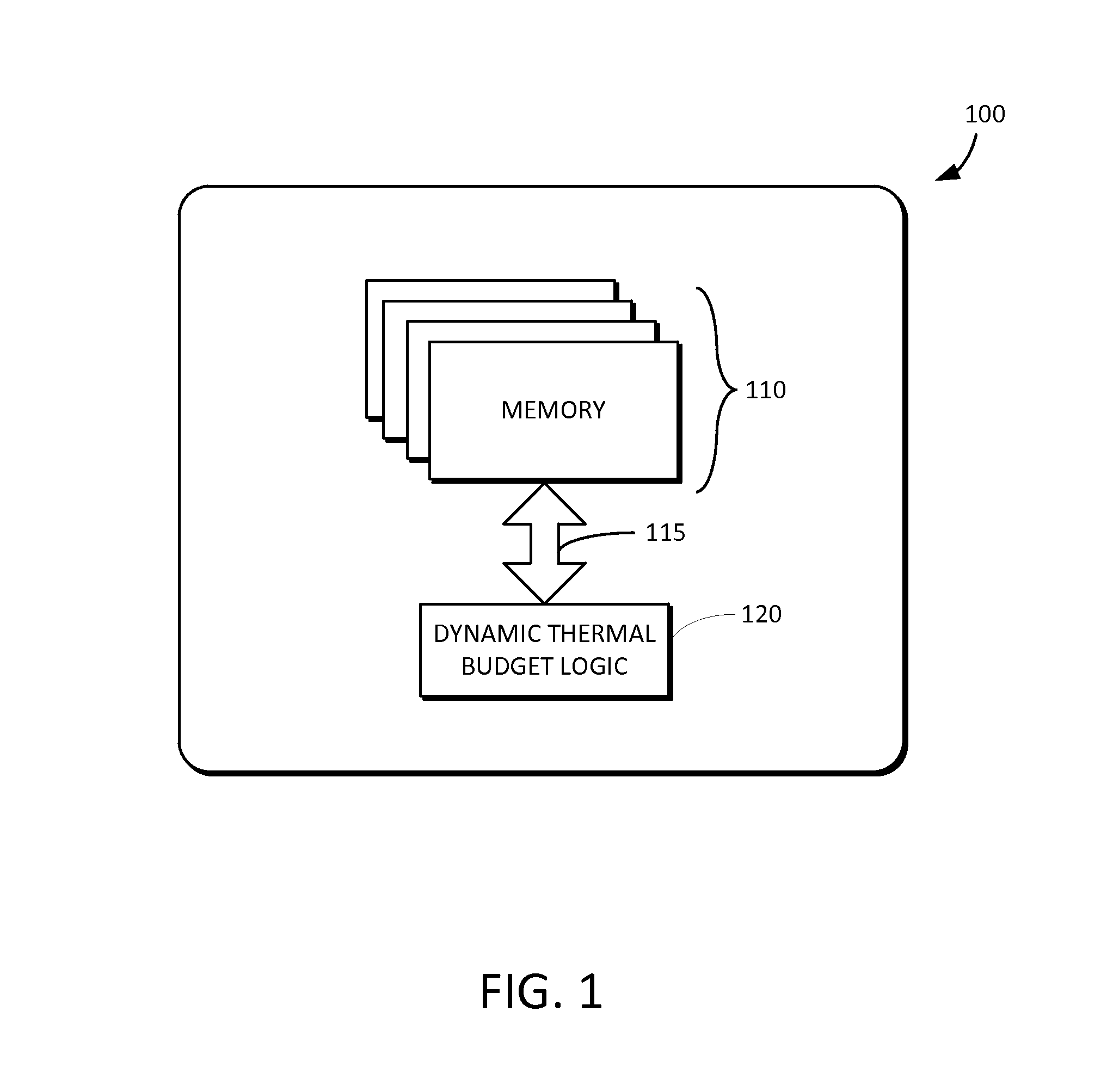
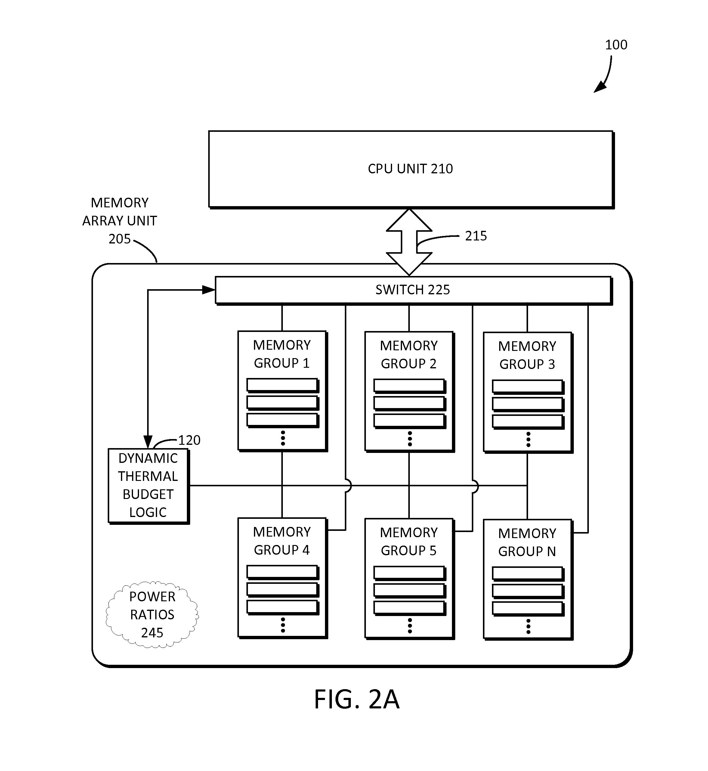
Embodiments of the present inventive concept relate to systems and methods for dynamically allocating and / or redistributing thermal budget to each memory group in a memory array from a total memory thermal budget based on the workload of each memory group. In this manner, the memory groups having a higher workload can receive a higher thermal budget. The allocation can be dynamically adjusted over time. Thus, the individual and overall memory group performance increases while efficiently allocating the total thermal budget. By dynamically sharing the total thermal budget of the system, the performance of the system as a whole is increased, thereby lowering, for example, the total cost of ownership (TCO) of datacenters.

Description

RELATED APPLICATION DATA[0001]This application claims the benefit of, commonly-owned U.S. Provisional Patent Application Ser. No. 61 / 921,463, filed Dec. 28, 2013, which is hereby incorporated by reference.BACKGROUND[0002]The present inventive concepts relate to systems having memory arrays, and more particularly, to methods and systems for dynamically allocating thermal budgets for systems containing multiple memory groups.[0003]Memory is a fundamental component of computers and computing. For example, a computer server can have multiple memory modules, memory arrays, memory groups, external memory units such as memory array boxes, or the like. By way of another example, mobile devices can have multiple embedded memory chips. In conventional systems that have memory groups, each memory group has its own fixed fraction of a total thermal budget. Each memory group evenly shares the total thermal budget, and each share is permanently fixed. The total thermal budget is based on worst ca...

Claims


Application Information

Patent Timeline
Patent Type & Authority Patents(United States)
IPC IPC(8): G06F1/00G06F1/32G06F1/20G06F3/06G06F12/06G06F12/02
CPCG06F1/206G06F1/329G06F1/3221G06F1/3225G06F1/3268G06F1/3275G06F3/06G06F12/06G06F12/02G06F2212/1028G06F3/0625G06F3/0634G06F3/067Y02D10/00
Inventor PING, ZHANBRENNAN, ROBERTMARTINEAU, JASON
Owner SAMSUNG ELECTRONICS CO LTD
Learn More