Liquid crystal display device and electronic device

a liquid crystal display and electronic device technology, applied in static indicating devices, instruments, optics, etc., to achieve the effect of suppressing the increase in the operation temperature of the transistor provided in each pixel, and reducing the amount of light emission

Active Publication Date: 2016-05-24
SEMICON ENERGY LAB CO LTD
View PDF158 Cites 16 Cited by
  • Summary
  • Abstract
  • Description
  • Claims
  • Application Information

AI Technical Summary

Benefits of technology

[0010]It is an object of an embodiment of the present invention to provide a transmissive liquid crystal display device in which power consumption is reduced and deterioration in display quality is suppressed.
[0011]It is a main point of an embodiment of the present invention to apply a light source for surface (planar) emission to a backlight of a transmissive liquid crystal display device which can control the frequency of inputting an image signal to a pixel.
[0014]A liquid crystal display device of an embodiment of the present invention applies a light source for surface emission to a backlight. The light source has a large light emission area because it is a light source which performs surface light emission. Therefore, the backlight can effectively radiate heat. That means the backlight is a backlight whose temperature increase in light emission is suppressed. Accordingly, in the liquid crystal display device, an increase in operation temperature of the transistor provided in each pixel can be suppressed. Therefore, an increase in off-state current of the transistor in the liquid crystal display device can be suppressed.
[0015]As described above, a liquid crystal display device of an embodiment of the present invention applies a light source which is excellent in heat radiation to a backlight. Thus, even in the case where an image signal is not input to a pixel for a long period, the pixel can hold an image signal. In other words, both a reduction in power consumption and a suppression of deterioration in display quality can be realized.

Problems solved by technology

Therefore, there is a strong trade-off between power consumption and display quality in the case where a transmissive liquid crystal display device is used for the liquid crystal display device disclosed in Patent Document 1.

Method used


Image

  • Liquid crystal display device and electronic device
  • Liquid crystal display device and electronic device
  • Liquid crystal display device and electronic device

Examples


modification example

[0107]A liquid crystal display device having the above-described structure is one embodiment of the present invention, and a liquid crystal display device different from the liquid crystal display device having the above-described structure in some points is included in the present invention.

Modification Example of Display Panel

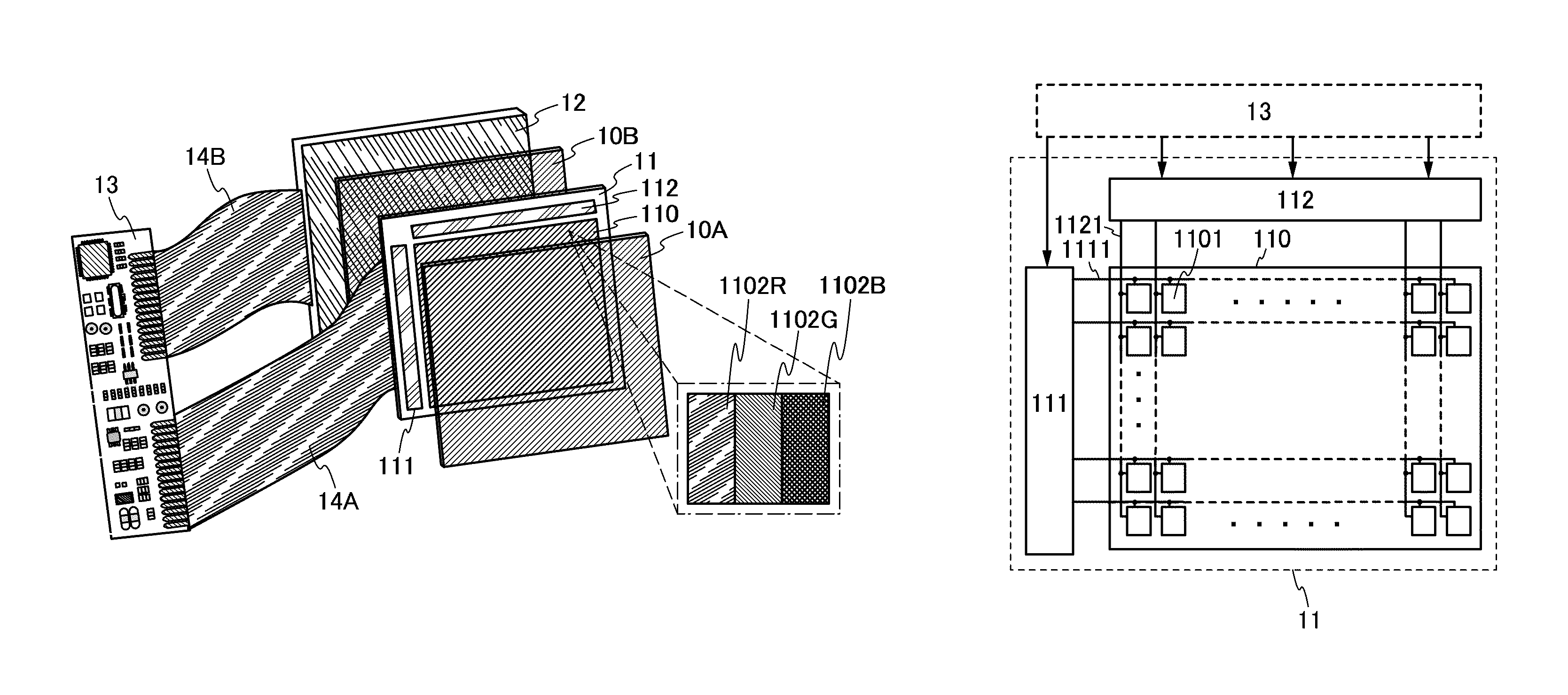
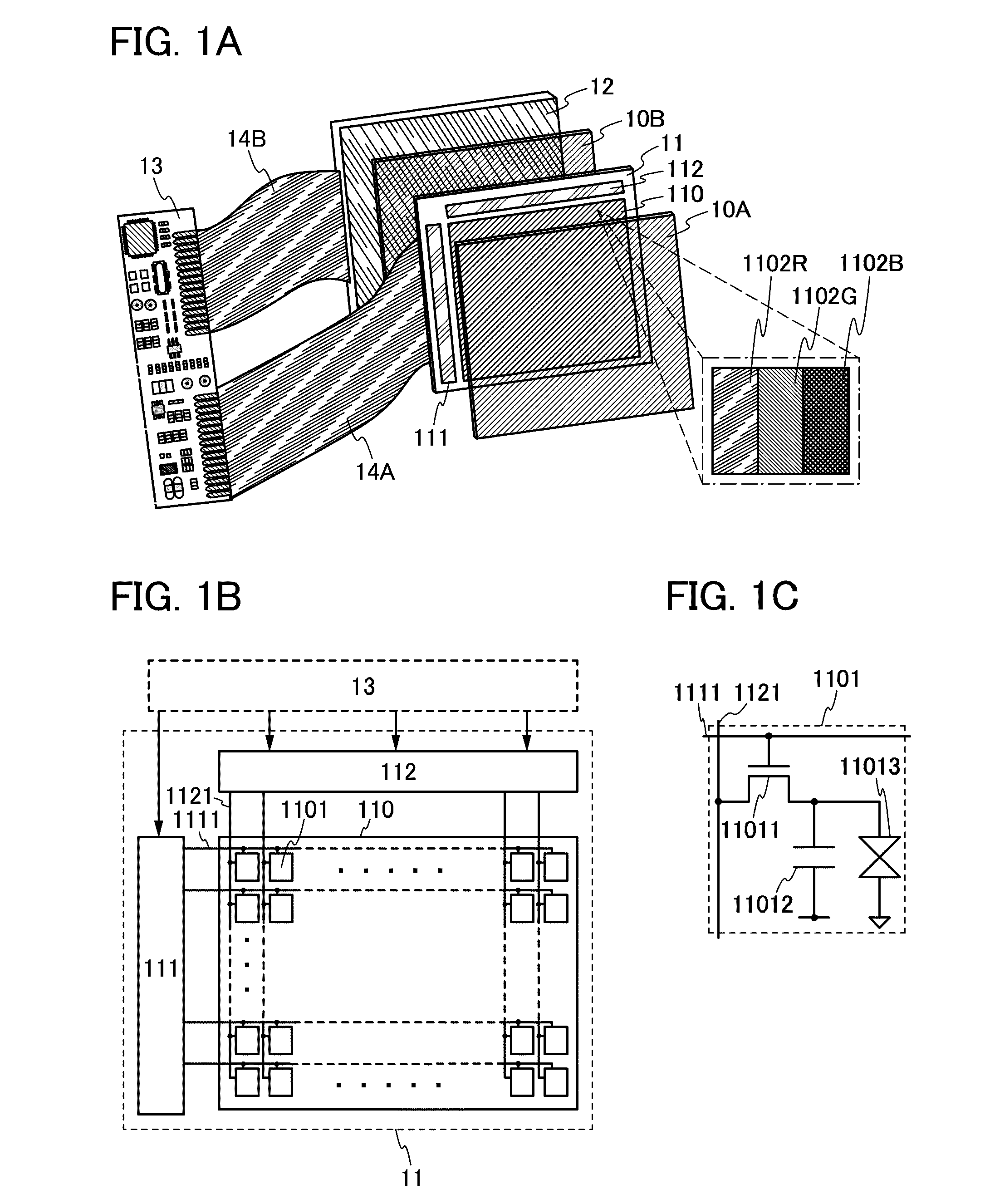
[0108]For example, the case is illustrated where the liquid crystal display device has a structure in which a color filter transmitting light with a wavelength of a given color is provided for each of a plurality of pixels arranged in matrix in the pixel portion of the display panel (see FIG. 1A). However, it is possible to have a structure where a color filter is not provided for part of the plurality of pixels. In other words, although the liquid crystal display device has a structure in which display is performed with the three colors of red (R), green (G), and blue (B), the liquid crystal display device may perform display with the four colors of red (R),...


PUM


Abstract

It is an object to provide a transmissive liquid crystal display device in which power consumption is reduced and deterioration in display quality is suppressed. As a backlight, a surface-emission light source is employed. The light source is a light source which performs surface light emission, so that the light emission area is large. Accordingly, the backlight can effectively radiate heat. Thus, even in the case where an image signal is not input to a pixel for a long period, the pixel can hold the image signal. In other words, both a reduction in power consumption and a suppression of deterioration in display quality can be realized.

Description

BACKGROUND OF THE INVENTION[0001]1. Field of the Invention[0002]The present invention relates to liquid crystal display devices. In particular, the present invention relates to a transmissive liquid crystal display device.[0003]2. Description of the Related Art[0004]Liquid crystal display devices are devices performing display by modulation of light with the use of liquid crystal materials whose alignment is controlled in accordance with applied voltage. Specifically, the liquid crystal display devices are roughly divided into two, depending on light used for display: external light such as natural light or interior lighting, or light emitted from light sources (backlights) included in the liquid crystal display devices itself. In general, the liquid crystal display devices which perform display with the use of the former are referred to as reflective liquid crystal display devices, and the liquid crystal display devices which perform display with the use of the latter are referred ...

Claims


Application Information

Patent Timeline
Patent Type & Authority Patents(United States)
IPC IPC(8): G09G3/36G09G3/34H05B44/00
CPCG09G3/3406G09G3/3648G09G2320/0214G09G2320/10G09G2330/021G09G2340/0435G02F1/133G02F1/1335G09G3/36G09G2300/0842G09G2320/0233G09G2320/04G09G2320/041G09G2330/023
Inventor YAMAZAKI, SHUNPEIKOYAMA, JUN
Owner SEMICON ENERGY LAB CO LTD
Why Eureka
Try Eureka