Boost pressure control system for turbocharged internal combustion engines

a control system and internal combustion engine technology, applied in the direction of valve operating means/release devices, functional valve types, machines/engines, etc., can solve the problems that the waste gate valve and its operating mechanism are a significant cost addition to the turbocharger, and achieve the effects of less complicated, less expensive materials, and cost saving

Inactive Publication Date: 2016-05-31
DELGADO LAUREN N
View PDF9 Cites 3 Cited by
  • Summary
  • Abstract
  • Description
  • Claims
  • Application Information

AI Technical Summary

Benefits of technology

[0010]The air that is bled from the engine intake manifold system has been cooled by passing through an air-to-air aftercooler where the cooling medium is ambient air. Thus, the compressed air to the engine is of the order of 100° F. to 140° F., depending on the ambient air temperature and the effectiveness of the aftercooler. This cooled air can be used effectively to cool the internal parts of a turbocharger.
[0011]The utilization of the novel adjustable bleed air valve in the engine air intake of this invention, downstream of an air-to-air aftercooler, is a unique method of preventing the turbocharger from exceeding its maximum speed limit and concurrently providing cooling air for the hot internal parts of a turbocharger. As previously stated, this invention eliminates the conventional waste gates and liquid coolant lines when liquid engine coolant is used to cool the hot internal parts of a turbocharger. Elimination of the waste gate results in a substantial cost saving since the adjustable boost pressure control valve is less complicated than a waste gate, has no connection with the hot exhaust parts of the turbocharger and can be made of less expensive materials than the exhaust gas by-pass valves or waste gates.

Problems solved by technology

The waste gate valve and its operating mechanism represent a significant cost addition to the turbocharger.

Method used


Image

  • Boost pressure control system for turbocharged internal combustion engines
  • Boost pressure control system for turbocharged internal combustion engines
  • Boost pressure control system for turbocharged internal combustion engines

Examples


Embodiment Construction

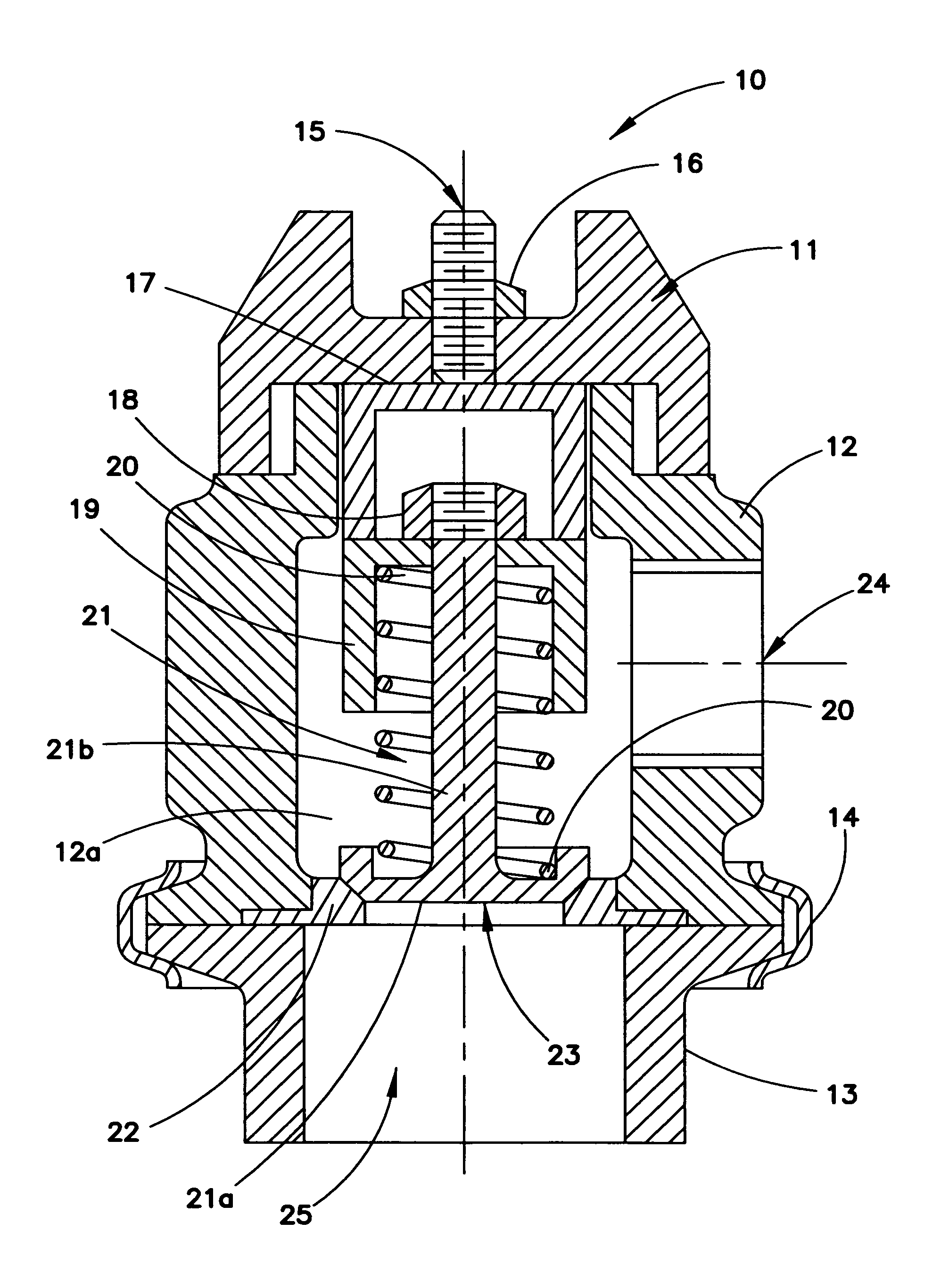
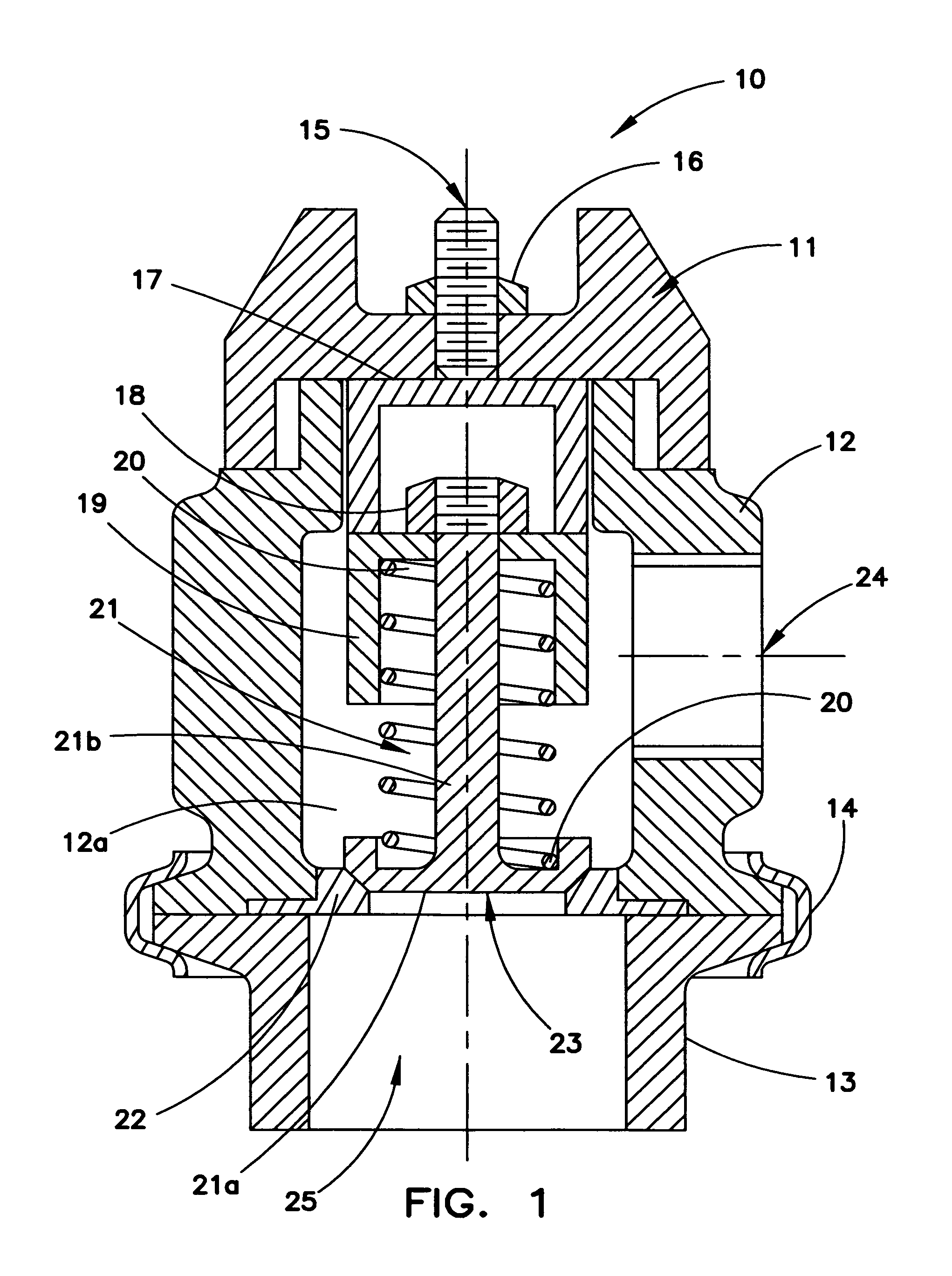
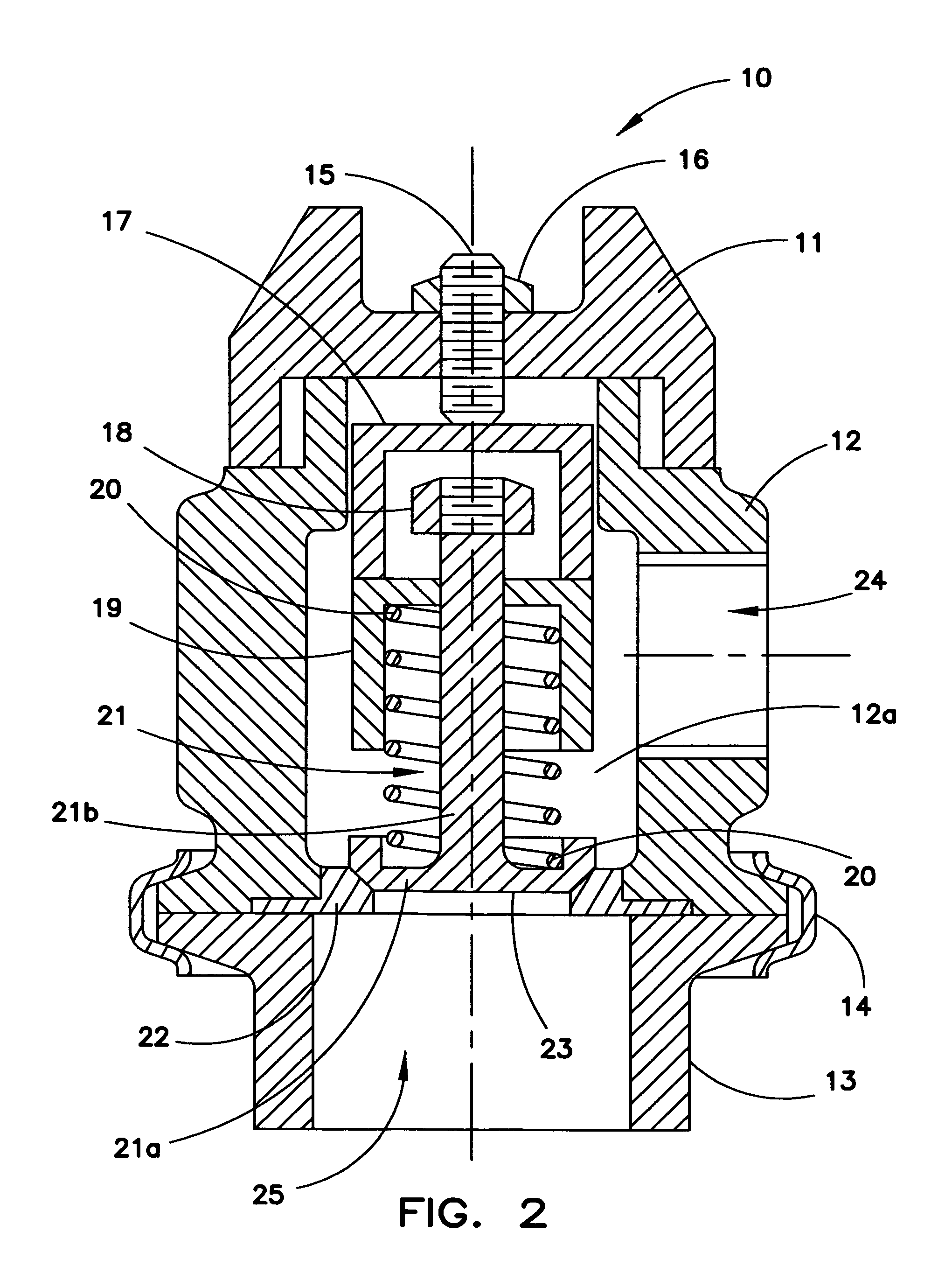
[0016]As noted above, this invention discloses a boost pressure control system for a turbocharged engine which may, in a preferred embodiment, provide a selectable constant boost pressure over the high speed range of the engine or, in another embodiment, provide a variable boost pressure over the high speed range of the engine.

[0017]FIG. 1 illustrates an embodiment of the constant pressure control valve 10. The control valve 10 comprises a valve cap 11, and a valve body 12 that house a spring-loaded valve 21 seated against a valve seat 22. The valve 21 includes a valve closure portion 21 a and a stem 21b projecting from the valve closure portion 21a, and a compression spring 20 surrounds and is carried by the valve 21. Spring 20 (coils not shown) is compressed to a fixed length by spring retainer 19 and nut 18. A piston 17 carried in a cylindrical portion 12a of the valve body 12, bears against spring retainer 19 and forces the spring retainer 19 to compress spring 20 to a fixed len...


PUM


Abstract

A variable boost pressure control system for turbocharged internal engine systems comprising an adjustable charge air vent valve connectable with the charge air input to an internal combustion engine to provide selection and adjustment of the charge air pressure to the internal combustion engine, either at the site of the charge air vent valve or at a location remote from the charge air vent valve and to provide, if desirable, a flow of cool charge air to a turbocharger cooling jacket.

Description

FIELD OF THE INVENTION[0001]This invention relates to turbocharged internal combustion engines that use waste gates as a means of limiting boost pressure (charge air pressure) over the high engine speed range of operation.BACKGROUND OF THE INVENTION[0002]Turbochargers that are used on both diesel and gasoline engines to increase power output and reduce fuel consumption are becoming more and more prevalent in the marketplace since they also contribute to lowering exhaust emissions. They will be a significant factor in meeting the federally mandated mileage and emission standards that must be met by 2016.[0003]Engines that are required to produce high power and high torque at low engine speeds, diesel truck engines for example, or passenger car engines that need to accelerate rapidly, require turbochargers that are capable of supplying high charge air pressure at low engine speeds, up to the torque peak speed of the engine. Above the torque peak speed, turbochargers with waste gates h...

Claims


Application Information

Patent Timeline
Patent Type & Authority Patents(United States)
IPC IPC(8): F02B33/44F16K15/06F16K31/14F16K31/122F02B37/16F16K17/06F02B39/00
CPCF16K15/063F02B37/16F02B39/005F16K17/06F16K31/1223Y02T10/144Y02T10/12
Inventor WOOLLENWEBER, WILLIAM E.DELGADO, JOSEPH S.
Owner DELGADO LAUREN N
Why Eureka
Try Eureka