
Heat exchanger

a heat exchanger and heat exchanger technology, applied in the field of high-efficiency furnaces, can solve the problems of high-cost materials, high-quality stainless steels, and high-temperature materials, and achieve the effects of less expensive materials, reduced use of high-cost materials, and easy fabrication

Active Publication Date: 2015-02-17
JOHNSON CONTROLS TYCO IP HLDG LLP
View PDF96 Cites 2 Cited by
  • Summary
  • Abstract
  • Description
  • Claims
  • Application Information

AI Technical Summary

Benefits of technology

This patent is about a method to prevent corrosion in an HVAC&R system. The method involves using a heat exchanger with corrosion-resistant bodies and a condensate collector. The heat transfer fluid is circulated through the heat exchanger without coming into contact with the first panel and second panel. The condensate collected in the collector is then managed to prevent its contact with the panel. The technical effect of this patent is to reduce the cost of the furnace system while maintaining the required corrosion resistance and heat resistance areas.

Problems solved by technology

One or more additional secondary heat exchangers may transfer additional heat from the gases from the primary heat exchanger to air in the air distribution system, typically resulting in condensation of the combustion gases.
In some cases, if the combustion air to the furnace is not clean, the condensed water or condensate can be corrosive.
Materials, such as high-grade stainless steels, that are both corrosion-resistant and heat-resistant, are expensive.

Method used


Image

  • Heat exchanger
  • Heat exchanger
  • Heat exchanger

Examples


Embodiment Construction

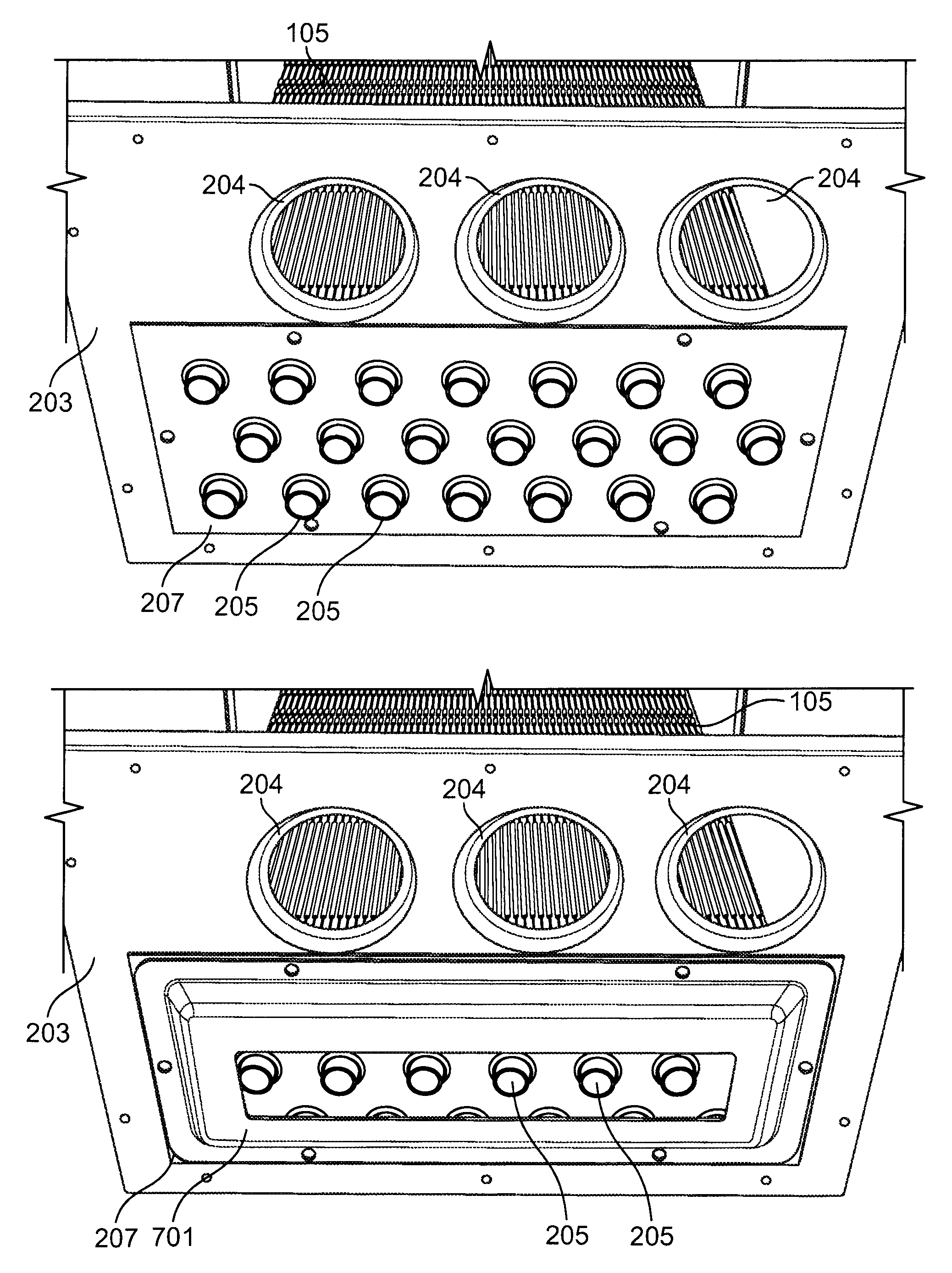
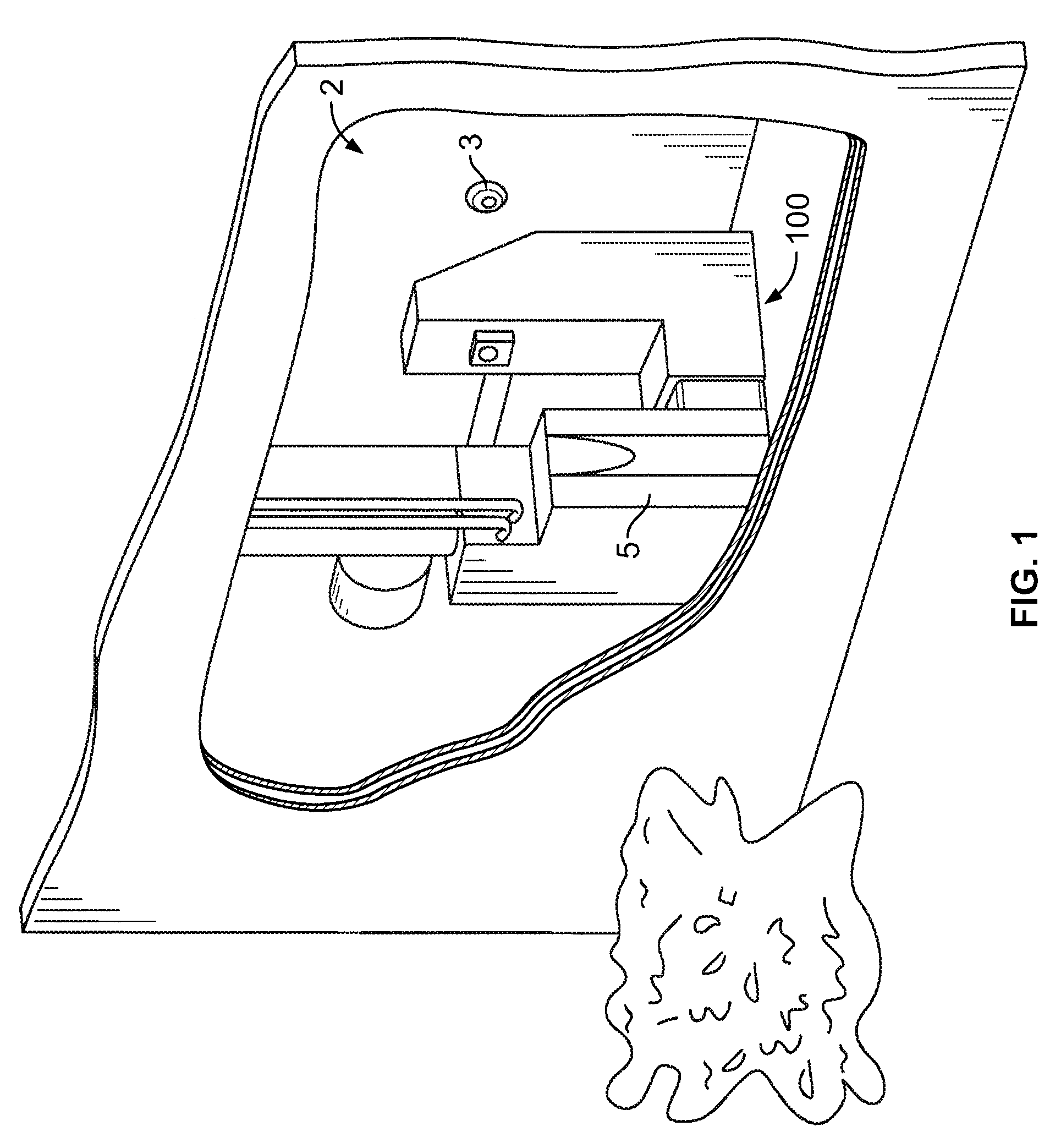
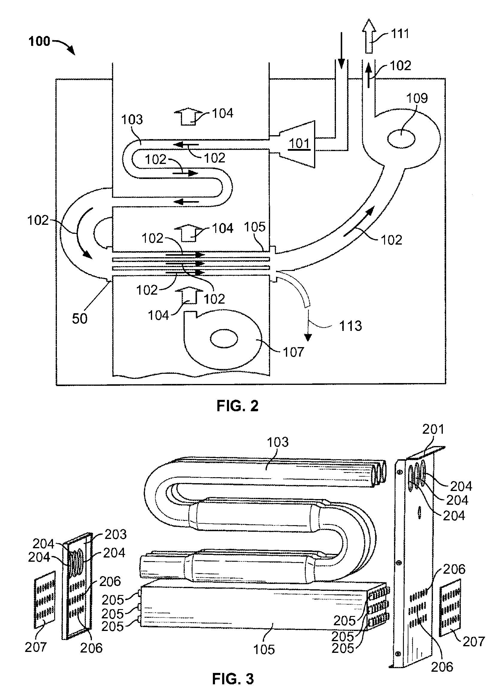
[0026]FIG. 1 shows an exemplary furnace 100 in a typical residential setting 2. Furnace 100 is disposed within an enclosed space of the residential setting 2. In furnace 100, air is drawn into furnace 100 and subsequently heated by exchanging heat with products of combustion generated by burning a fuel in furnace 100. A thermostat 3 or similar device that monitors and controls the conditions within the enclosed space may be used to provide temperature control to the enclosed space by controlling the operation of furnace 100. An air distribution system 5 including an air mover such as a blower or other similar device may be used to distribute air to the enclosed space in residential setting 2. In another embodiment, furnace 100 can be incorporated in a heating, ventilation and air conditioning system for the enclosed space. The heating, ventilation and air conditioning system can provide both heating to the enclosed space using furnace 100 and cooling to the enclosed space using a va...


PUM

PropertyMeasurementUnit
corrosion resistantaaaaaaaaaa
surface areaaaaaaaaaaa
corrosiveaaaaaaaaaa

Abstract

A furnace or other heat exchanger application for heating, ventilation, air conditioning and refrigeration systems having condensate control. Specifically, a condensate control for secondary heat exchangers is provided for use with high efficiency furnaces, particularly for small tonnage systems, such as residential or unitary systems. Condensate management permits a plurality of furnace orientations while providing resistance to corrosion due to liquid condensate.

Description

CROSS REFERENCE TO RELATED PATENT APPLICATIONS[0001]This application is a continuation of application Ser. No. 12 / 141,366, filed Jun. 18, 2008, entitled HEAT EXCHANGER, which claims the benefit of U.S. Provisional Application No. 60 / 945,698, filed Jun. 22, 2007, entitled FURNACE HEAT EXCHANGER CONDENSATE CONTROL, both of which Applications are herein incorporated by reference in their entirety.BACKGROUND[0002]The present application relates generally to high efficiency furnaces and applications utilizing condensation of combustion gases in heating, ventilation, air conditioning and refrigeration systems.[0003]The basic components of a furnace system include a burner, at least one heat exchanger, an air distribution system, and an exhaust. In the burner, gas, such as natural gas or propane, oil or other fuel is delivered and burned to generate heat. A primary heat exchanger transfers heat from the burning gas to the air distribution system. One or more additional secondary heat excha...

Claims


Application Information

Patent Timeline
Patent Type & Authority Patents(United States)
IPC IPC(8): F24H3/00F23M5/00F24H3/08F24H8/00F28D7/16F28F17/00
CPCF23M5/00F24H3/087F24H8/00F28D7/1615F28F17/005Y02B30/102F28F19/00Y02B30/00Y10T29/4935Y10T29/49364B23P15/26F25D21/14F28F1/12F28F21/08
Inventor KHAN, TABRAIZ ALICABRERA, ROBERTREASER, GREGORY KENNETHHILL, TERRY
Owner JOHNSON CONTROLS TYCO IP HLDG LLP
Learn More