
Abrasive media blasting method and apparatus

a blasting nozzle and abrasive media technology, applied in the direction of blast guns, metal-working equipment, manufacturing tools, etc., can solve the problems of remarkably inefficient energy transfer, unable to solve at least three of the historic difficulties of these and other shot, sand or hard media blasting nozzles

Active Publication Date: 2019-05-09
ARBORJET
View PDF5 Cites 2 Cited by
  • Summary
  • Abstract
  • Description
  • Claims
  • Application Information

AI Technical Summary

Benefits of technology

The invention describes a new blasting nozzle design that uses a supersonic nozzle to achieve high velocity air for blasting without the need for expensive media wear on the nozzle. The nozzle is shorter and can be made from less expensive materials. The nozzle is decoupled from the media acceleration function, allowing for independent optimization of each. The design also allows for the introduction of abrasive media through a small diameter hose, introducing a small quantity of atmospheric air. The system includes a replaceable wear tip at the exit of the acceleration chamber and an adjustable and flexible shield to protect the operator. These technical effects improve performance and cost-effectiveness in blasting applications.

Problems solved by technology

A significant problem associated with the long-venturi nozzle is that it is remarkably inefficient with regard to the transfer of energy from the compressed airstream flowing through the nozzle to the abrasive particles entrained therein.
Thus, 95% of the kinetic energy of the air stream is being lost in such nozzle designs.
The media blast PS nozzle design of the '966 patent is a step forward in the design of such nozzles, but, it failed to solve at least three of the historic difficulties of these and other shot, sand or hard media blasting nozzles.
These are: (1) nozzle wear at the throat, (2) continuously wear through the nozzle expansion region and (3) wear at the exit diameter, all caused by the media passing through the nozzle.
Further as each internal diameter between the throat and the nozzle exit is initially different from every other internal diameter for appropriate velocity development, even uniform internal nozzle wear, which will not occur, results in disproportional wear from a design and performance perspective.
Nozzle wear will not be uniform since it is a function of initial and subsequent velocity plus initial and subsequent diameter at every location along the nozzle axis between the throat and the nozzle exit.
These issues are well known in the industry, and lead to material composition, hardness and cost trade-offs in nozzle design and frequency of nozzle replacement.
No material lasts forever in this type of application especially when media materials such as steel shot and sand are employed.
This produces serious mismatches between available compressor power and nozzle configuration resulting in continuous wasted power during almost every blasting nozzle use, regardless of type.

Method used


Image

  • Abrasive media blasting method and apparatus
  • Abrasive media blasting method and apparatus
  • Abrasive media blasting method and apparatus

Examples


Embodiment Construction

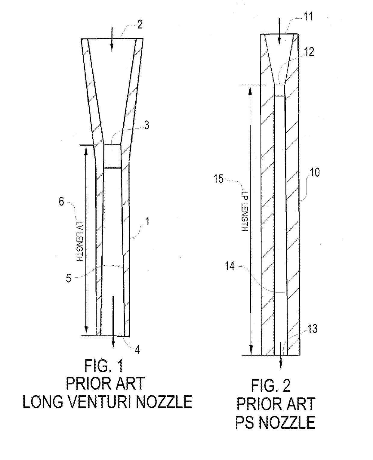
[0035]Referencing the figures, FIG. 1 is a schematic side section view of a prior art Long Venturi nozzle 1 discussed above, and used herein for comparison. A commercial long venturi nozzle 1 viewed in cross section is shown and has a venturi nozzle entrance 2, a venturi nozzle throat 3 to increase air velocity and a venturi nozzle exit 4, usually larger than the throat, a venturi nozzle expansion 5, and an LV length 6,

[0036]FIG. 2 is a schematic side section view of a prior art P.S. Nozzle 10 discussed above and used herein for comparison. A P.S. nozzle 10 has a P.S. nozzle entrance 11, a P.S. nozzle throat 12, a P.S. nozzle exit 13, a P.S. nozzle expansion 14 and an LP length 15.

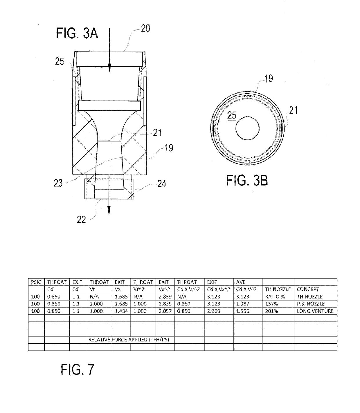
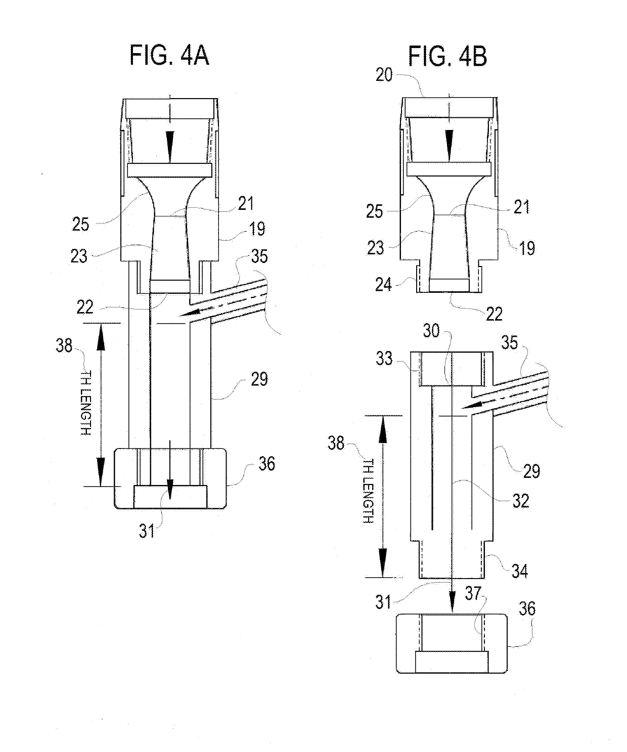
[0037]FIGS. 3 A and B are a schematic side section and top plan views, respectively, of a supersonic nozzle 19 forming one component of an apparatus for use in abrasive media blasting in accordance with one embodiment of the present invention. The supersonic nozzle 19 has a supersonic nozzle entrance 20, a...


PUM

PropertyMeasurementUnit
axial lengthaaaaaaaaaa
areaaaaaaaaaaa
gravityaaaaaaaaaa

Abstract

An improved media blasting system that separates the fluid velocity development, the introduction of media and the acceleration of media from each other. The preferred arrangement has a supersonic nozzle that produces supersonic velocity air discharged into a coupled acceleration chamber. No shot travels within the supersonic nozzle, so no wear of the supersonic nozzle interior occurs, thus making the nozzle shorter, of plain metal alloys, less expensive to manufacture and lasting indefinitely. The shot is separately introduced into the acceleration chamber thus avoiding it's otherwise limitation to the air mass flow rate in the air supply hose or pipe. Thus the average velocity used to transfer momentum to the shot is much higher than the lower average velocity currently available within other blasting nozzles, which occurs from throat to exit. Further, the nozzle design parameters are selected to match the higher maximum power output of a selected air compressor and are not constrained by nozzle wear factors requiring frequent replacement of the nozzle for reasons of nozzle wear.

Description

CROSS REFERENCE TO RELATED APPLICATIONS[0001]The present application claims priority to provisional patent application Ser. No. 62 / 511,752 filed May 26, 2017 entitled “Abrasive Media Blasting Method and Apparatus” which is incorporated herein by reference.BACKGROUND OF THE INVENTION1. Field of the Invention[0002]The present invention relates to abrasive media blasting and more particularly to shot and sand blasting devices and associated methods.2. Background Information[0003]Abrasive media blasting have been used extensively for many years and generally may be described as forcibly propelling a stream of abrasive material against a surface under high pressure to smooth a rough surface, roughen a smooth surface, shape a surface, or remove surface contaminants. A pressurized fluid, typically compressed air, or a centrifugal wheel is used to propel the blasting material (often called the media).[0004]The first abrasive blasting process was patented by Benjamin Tilghman in 1870. Regard...

Claims


Application Information

Patent Timeline
Patent Type & Authority Applications(United States)
IPC IPC(8): B24C5/04B24C1/10
CPCB24C5/04B24C1/10
Inventor HURSEN, THOMAS FRANCIS
Owner ARBORJET
Learn More