Light source with laser pumping and method for generating radiation

a laser pumping and light source technology, applied in the direction of plasma technique, gas discharge lamp details, electrical apparatus, etc., can solve the problems of insufficient high operating stability in long-term continuous mode with high effectiveness, optimal configuration, and insufficient high stability output characteristics of high brightness light source, etc., to achieve high stability, high brightness, and long life.

Active Publication Date: 2016-05-31
OBSHCHESTVO S OGRANICHENNOJ OTVETSTVENNOSTJU RND ISAN
View PDF3 Cites 5 Cited by
  • Summary
  • Abstract
  • Description
  • Claims
  • Application Information

AI Technical Summary

Benefits of technology

[0014]The object of the invention is to create a highly stable compact light source with very high brightness and long lifetime and a method for generating radiation.
[0015]The technical result of the invention is increased spatial and energy stability of the high-brightness light source with laser pumping and increased reliability of operation.
[0018]Particularly, the region of radiating plasma is positioned at a minimal distance from the top wall of the chamber to avoid causing significant negative effects on the lifetime of the light source with laser pumping.

Problems solved by technology

A drawback of the specified device, and methods, created over 40 years ago, was insufficiently high operating stability in long-term continuous mode with high effectiveness.
However, the geometry of the light source determined by the direction of the laser beam and the position of the region of radiating plasma, created in the discharge gap for starting ignition of the plasma, is not optimal for achieving high stability output characteristics of a high brightness light source.
Although this device and method, in principle, make it possible to vary, within sufficiently wide limits, the geometry of the high brightness light source, the optimal configuration for minimizing the negative effect of convective streams of gas in the chamber on the output parameters of the radiation has not been overcome.
This leads to the possibility of sufficiently high energy and spatial instability of the light source caused by convection of gas in the chamber and limiting the range of its applications.
However, the geometry of the light source is not optimal and does not reduce the instability or noise, resulting from intense turbulent streams of gas in the chamber due to heat convection in the gravity field.
This reduces the possibility of effectively suppressing instability of output parameters of the light source with laser pumping, even using the feedback device.

Method used


Image

  • Light source with laser pumping and method for generating radiation
  • Light source with laser pumping and method for generating radiation
  • Light source with laser pumping and method for generating radiation

Examples


Embodiment Construction

[0045]This description is intended to illustrate implementation of the invention and not the entire scope of the present invention.

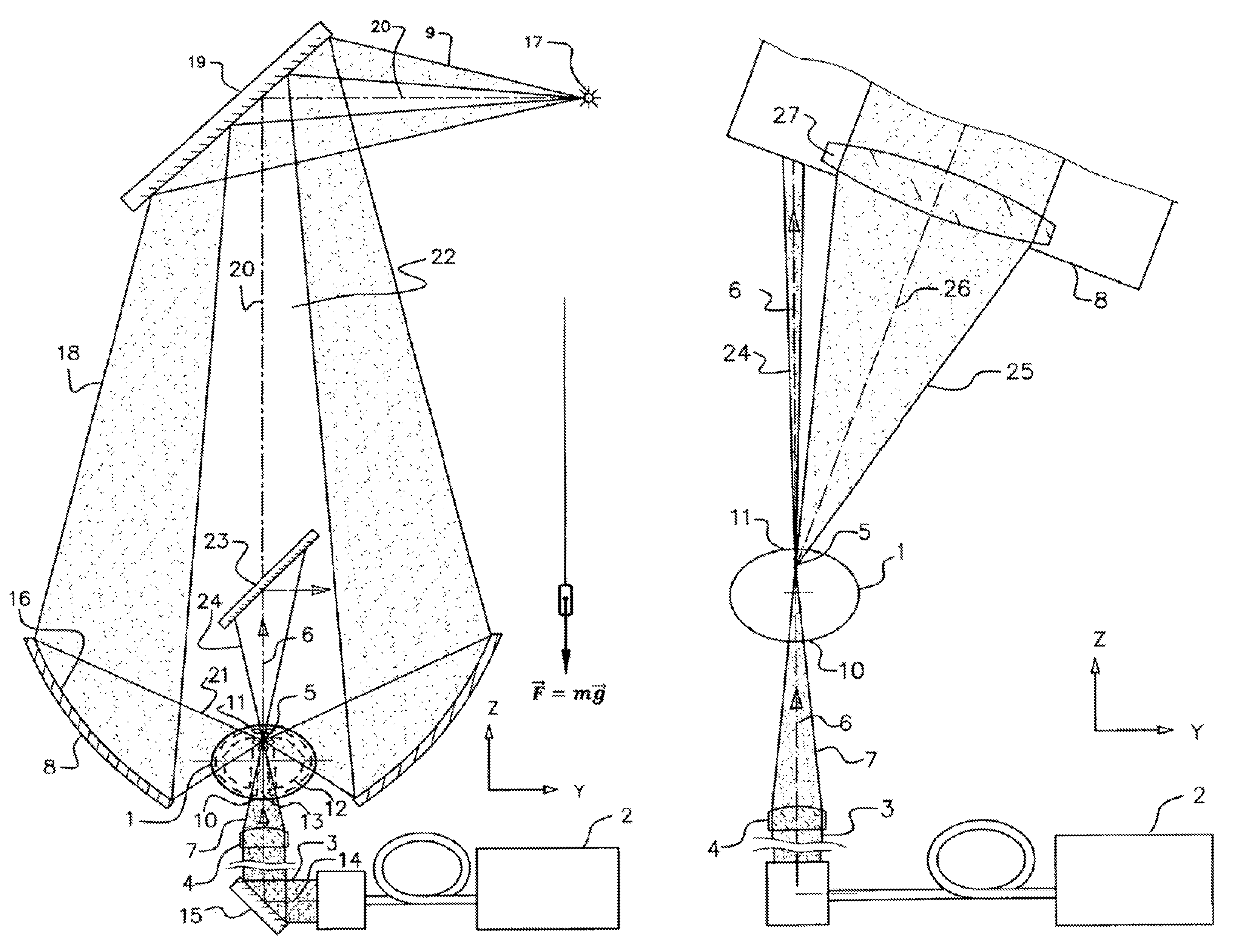
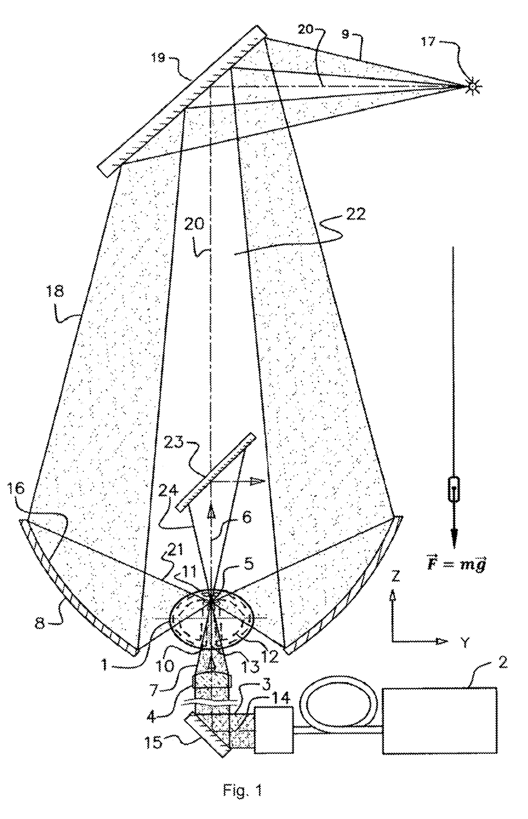
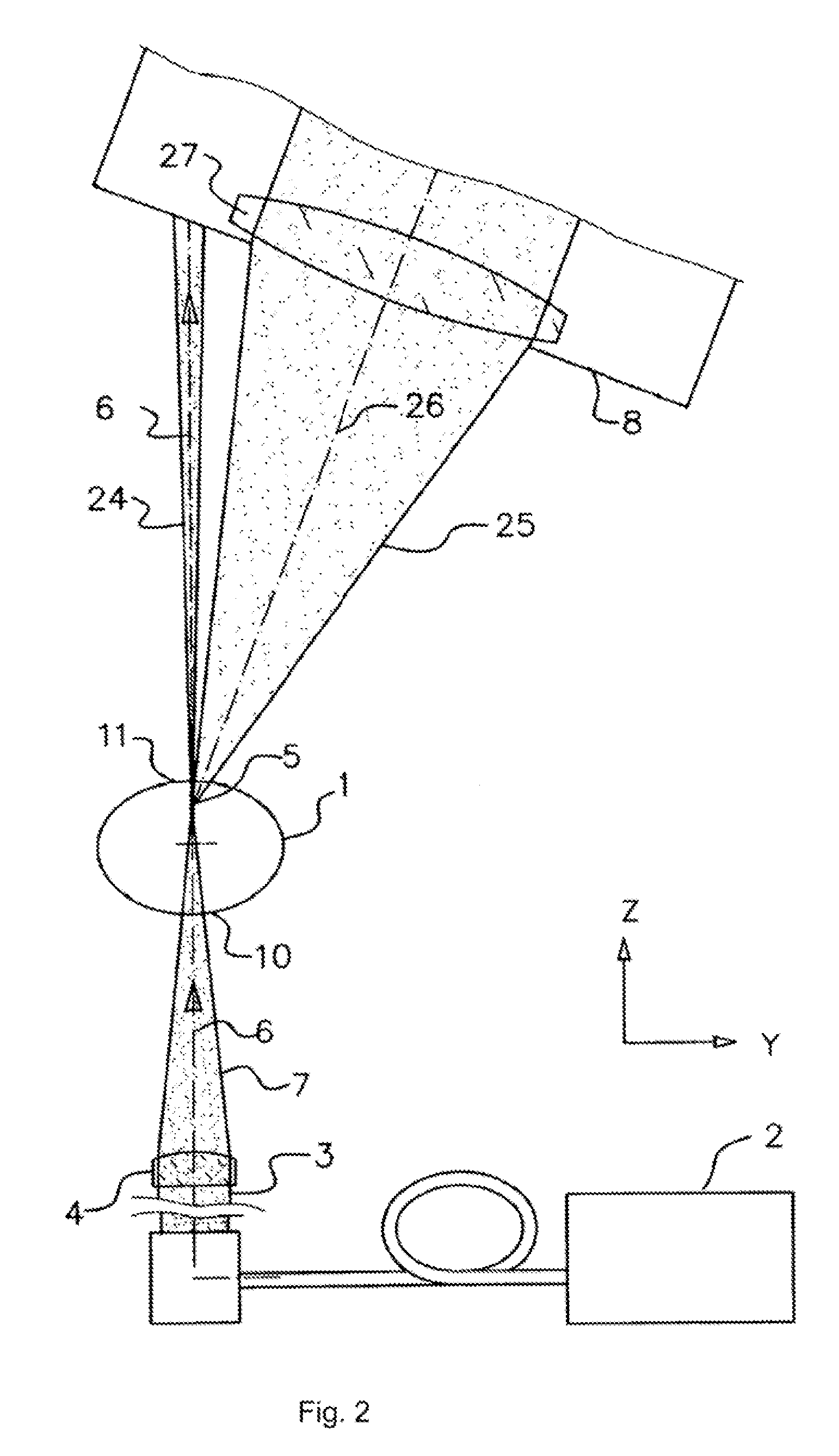
[0046]In accordance with the example of invention embodiment shown in FIG. 1, the light source with laser pumping comprises a chamber 1, containing gas; laser 2, generating a laser beam 3; optical element 4, focusing the laser beam; region of radiating plasma 5, formed in chamber 1 along the axis 6 of the focused laser beam 7; and optical system 8 for collecting plasma radiation, forming the beam of plasma radiation 9. The focused laser beam 7 is directed into the region of radiating plasma 5 from the bottom upwards: from the lower chamber wall 10 to the opposite upper wall 11 of the chamber 1. The region of radiating plasma 5 is positioned at a distance from the upper chamber wall 11 less than the distance from the region of radiating plasma 5 to the lower chamber wall 10.

[0047]On FIG. 1, as in other illustrations, the Z axis coordinate, parallel to the...


PUM


Abstract

Invention provides extending the functional possibilities of a light source with laser pumping due to increasing its spatial and energy stability brightness and the reliability under long-term operation whilst ensuring compactness of the device. The result is achieved due to the fact that a focused laser beam is directed into a region of radiating plasma from the bottom upwards: from the lower wall of a chamber to an upper wall of the chamber which is opposite said lower wall, and the region of radiating plasma is arranged close to the upper wall of the chamber. In embodiments of the invention, the focused laser beam is directed along a vertical axis of symmetry of the walls of the chamber, the region of radiating plasma is produced at an optimally small distance away from the upper wall of the chamber and determined radiation power is maintained via an automated control system.

Description

CROSS-REFERENCE TO RELATED APPLICATIONS[0001]Current patent application is a National stage application from PCT application No. PCT / RU2014 / 000257 filed on Apr. 8, 2014 which claims priority to the Russian patent application No. 2013116408 filed on Apr. 11, 2013.FIELD OF THE INVENTION[0002]The invention relates to a device of light sources with laser pumping and to methods for generating radiation with a high level of brightness in the UV and visible spectral ranges.PRIOR ART[0003]Optical discharge may be used as a light source with a high level of brightness since the temperature of the plasma in the optical discharge is significantly greater than in others—15000-20000 K, whereas an arc is usually between 7000-8000 K, HF discharge—9000-10000 K. Optical discharge plasma in various gases, in particular, in xenon Xe, created by beam of a continuous wave laser at gas pressures of 10-20 atm., is one of the highest-brightness sources of continuous radiation in the wide spectral range of ...

Claims


Application Information

Patent Timeline
Patent Type & Authority Patents(United States)
IPC IPC(8): H01J17/04H01J61/02H01J65/04H05H1/24H01J61/52H05H1/48H01J61/54H01J61/76
CPCH05H1/24H01J61/025H01J61/523H01J61/54H01J61/545H01J61/76H01J65/04H05H1/48
Inventor ANTSIFEROV, PAVEL STANISLAVOVICHKOSHELEV, KONSTANTIN NIKOLAEVICHKRIVTSUN, VLADIMIR MIKHAILOVICHLASH, ALEKSANDR ANDREEVICH
Owner OBSHCHESTVO S OGRANICHENNOJ OTVETSTVENNOSTJU RND ISAN
Why Eureka
Try Eureka