Axial-flow blood pump

a blood pump and axial flow technology, applied in the field of axial flow blood pumps, can solve the problems of high cost, high cost, and inability to implant such a known blood pump in a minimally invasive implanting method, and achieve the effect of avoiding invasive surgeries such as sternotomy or throracotomy

Active Publication Date: 2016-06-21
MAGASSIST CO LTD
View PDF2 Cites 36 Cited by
  • Summary
  • Abstract
  • Description
  • Claims
  • Application Information

AI Technical Summary

Benefits of technology

[0016]In another embodiment the supporting elements may be detachable from the anchoring system and attachable to the said anchoring system. This allows detaching the pump device from the anchoring system at a certain time of usage in particular after full recovery of the heart or any emergency situations and removing the device from the patient and maintaining the anchoring system at its location where it is originally implanted.
[0017]In any way the supporting elements keep the axial and radial alignment of the pump device in the anchoring system. The profile of the supporting elements is preferably designed to overcome the load generated during the pump operation including the axial thrust force, fluid drag force, and radial twisting force. In a preferred embodiment, the supporting elements, in particular their cross section may have fluid dynamic shape to improve the pump efficiency.
[0023]A possible embodiment exists according to which the pump device may be inserted / implanted first into a peripheral vessel (like femoral or jugular vein) of a smaller diameter and then anchored in a main vessel (like pulmonary artery) of a larger diameter. This means the pump device has two distinct states, one has smaller size for implantation and explantation procedure and the other has a recovered size for operation. This reduceable size of the device allows for implanting the device with a minimally invasive method, for example by using a catheter.
[0028]Since the hydraulic loading may vary over the blade surface due to the nature of blade geometry and flow velocity, further reinforcement can be added within certain regions of the blade surface or the said framework in particular to avoid deformation during pump operation. This therefore avoids impaired pump efficiency resulting from deformation. Reinforcement may be realized by rods or plates of various dimensions interconnecting different areas / parts of the framework.
[0029]In a preferred embodiment the at least one cantilever or framework and the hub of the impeller may be covered with a biocompatible material, in particular with a flexible or elastic material. This material may also form a smooth surface for optimal flow path when the whole device is unfolded after implantation. Such a flexible or elastic material furthermore may sustain higher mechanical strain and stress without any plastic deformation thus allows for a better folding, when the device is collapsed / compressed / folded.
[0030]Preferably the elastic / flexible material also totally covers the joint / hinge at the proximal end of the cantilever or framework where it is connected to the hub and generates a smooth and streamline-optimized blood contacting surface. This prevents blood from clotting since it cannot get in contact with this hinge area.

Problems solved by technology

As a consequence these blood pumps have a big volume requiring a placement in the thorax or abdomen and making it impossible to implant such a known blood pump in a minimally invasive implanting method.
The duration of support and patient's quality of life is highly restricted by the extracorporal components, such as the drive and console.
Implantable blood pumps exist; however, invasive surgeries, such as sternotomy or throracotomy, are required.

Method used


Image

  • Axial-flow blood pump
  • Axial-flow blood pump
  • Axial-flow blood pump

Examples


Embodiment Construction

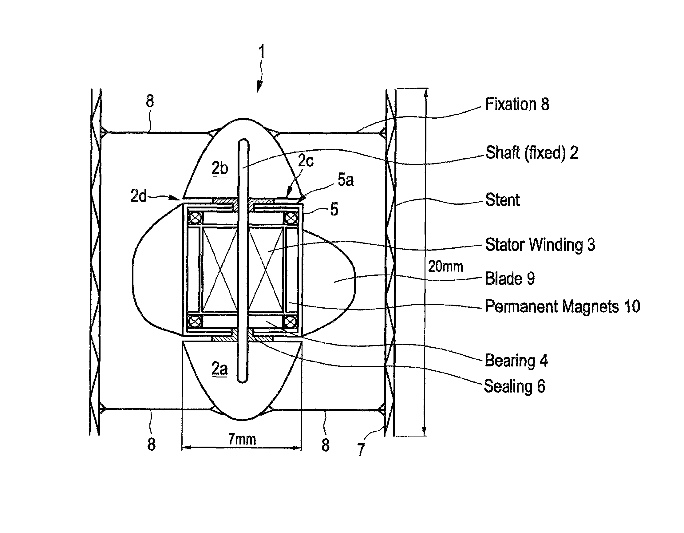
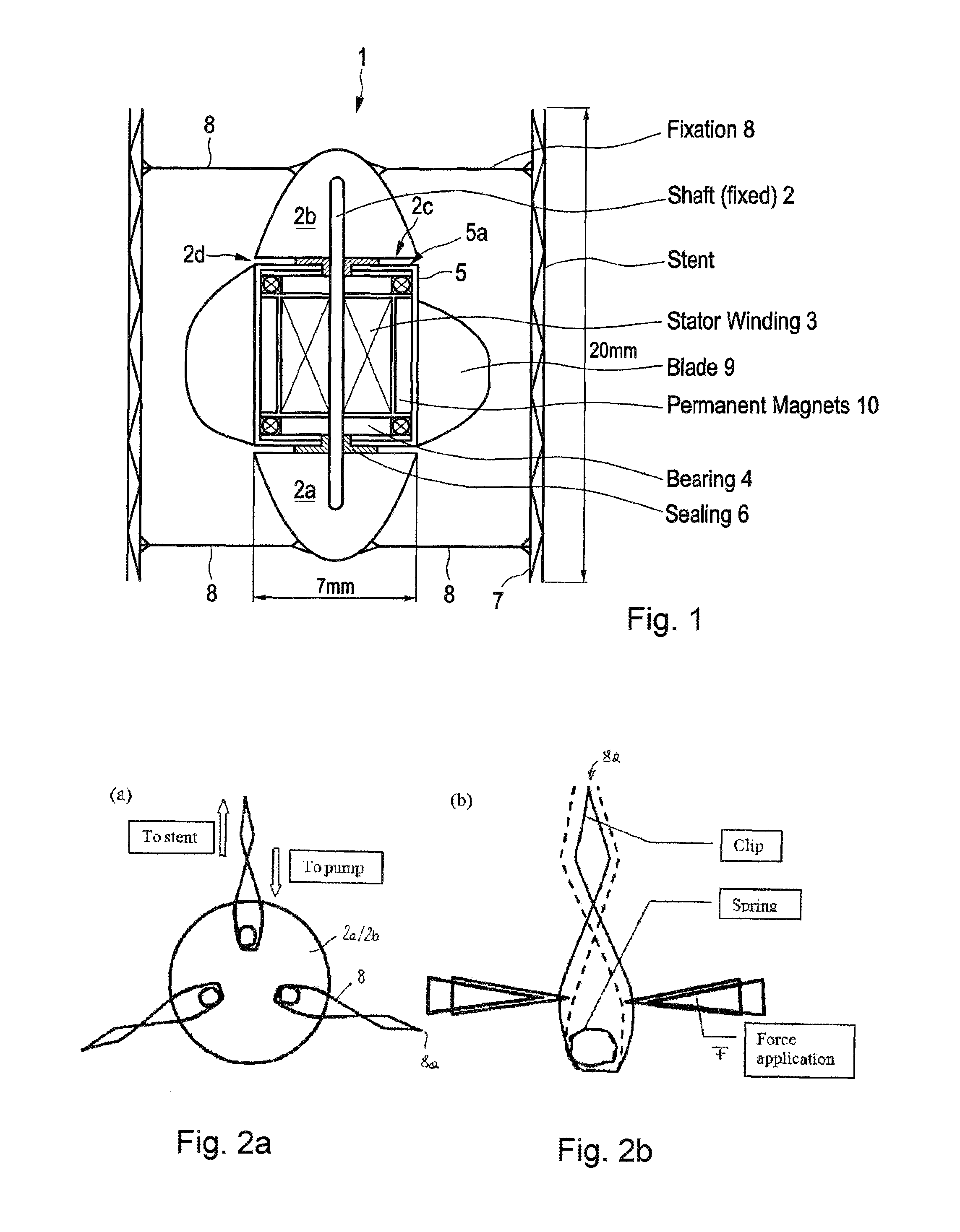
[0039]FIG. 1 shows a cross-sectional view of one possible embodiment of the inventive blood pump 1 when it is coaxially located within the interior of an anchoring system 7 like a stent 7 implanted in a vessel (not shown).

[0040]The blood pump 1 comprises a fixed, stationary shaft 2 surrounded by stator windings 3 being held by at least one not shown winding holder and a bearing system comprising two bearings 4 near each axial end of the stator windings 3. Accordingly in operation of the device the shaft is not moving at all (with respect to the patient / vessel).

[0041]By means of these bearings 4 an impeller hub 5 is rotatable supported on this shaft 2. Any free spaces between the shaft 2 and the impeller hub 5 surrounding the shaft 2 may be closed by seals 6.

[0042]According to FIG. 1 respective end parts 2a and 2b cover the respective ends of the shaft 2 and are attached to the anchoring system 7 by means of supporting elements 8 which in this case extend essentially in radial direct...


PUM


Abstract

An axial-flow blood pump has a rotatable impeller assembly rotatable about an axis and itself having a radially projecting blade and permanent magnets, A stationary stator assembly has stator windings interacting with the permanent magnets and a bearing system supporting the rotatable impeller assembly for rotation about the axis relative to the stator assembly. A stent implantable into a blood vessel is connected to ends of supports for coaxially mounting the stator assembly carrying the impeller assembly in the stent.

Description

CROSS REFERENCE TO RELATED APPLICATIONS[0001]This application is the US-national stage of PCT application PCT / EP2013 / 002120 filed 17 Jul. 2013 and claiming the priority of European patent application 12005545.4 itself filed 31 Jul. 2012.FIELD OF THE INVENTION[0002]The invention relates to an axial flow blood pump comprising an electromagnetic drive with a stationary stator assembly and a rotatable impeller assembly, wherein the stationary stator assembly at least comprises stator windings and a bearing system supporting the rotatable impeller assembly, the impeller assembly comprising at least one blade and permanent magnets interacting with the stator windings.BACKGROUND OF THE INVENTION[0003]Blood pumps of this kind are commonly known in the art and typically used to bridge a patient to recovery or heart transplantation in any kind of heart failure situations, particularly the end-stage patients who do not respond to medications.[0004]Typically blood pumps of the common kind compr...

Claims


Application Information

Patent Timeline
Patent Type & Authority Patents(United States)
IPC IPC(8): A61M1/12A61M1/10A61F2/82
CPCA61M1/125A61M1/1024A61M1/1029A61M1/1036A61F2/82A61M1/101A61M1/122A61M2205/04A61M2205/103A61M2210/12A61M60/829A61M60/422A61M60/419A61M60/148A61M60/135A61M60/808A61M60/827A61M60/237A61M60/825
Inventor HSU, PO-LINSTEINSEIFER, ULRICHPARKER, JACKAUTSCHBACH, RUEDIGER
Owner MAGASSIST CO LTD
Why Eureka
Try Eureka