

Method of manufacturing fuel system part and fuel system part
- Summary
- Abstract
- Description
- Claims
- Application Information
AI Technical Summary
Benefits of technology
Problems solved by technology
Method used
Image

Examples
embodiment
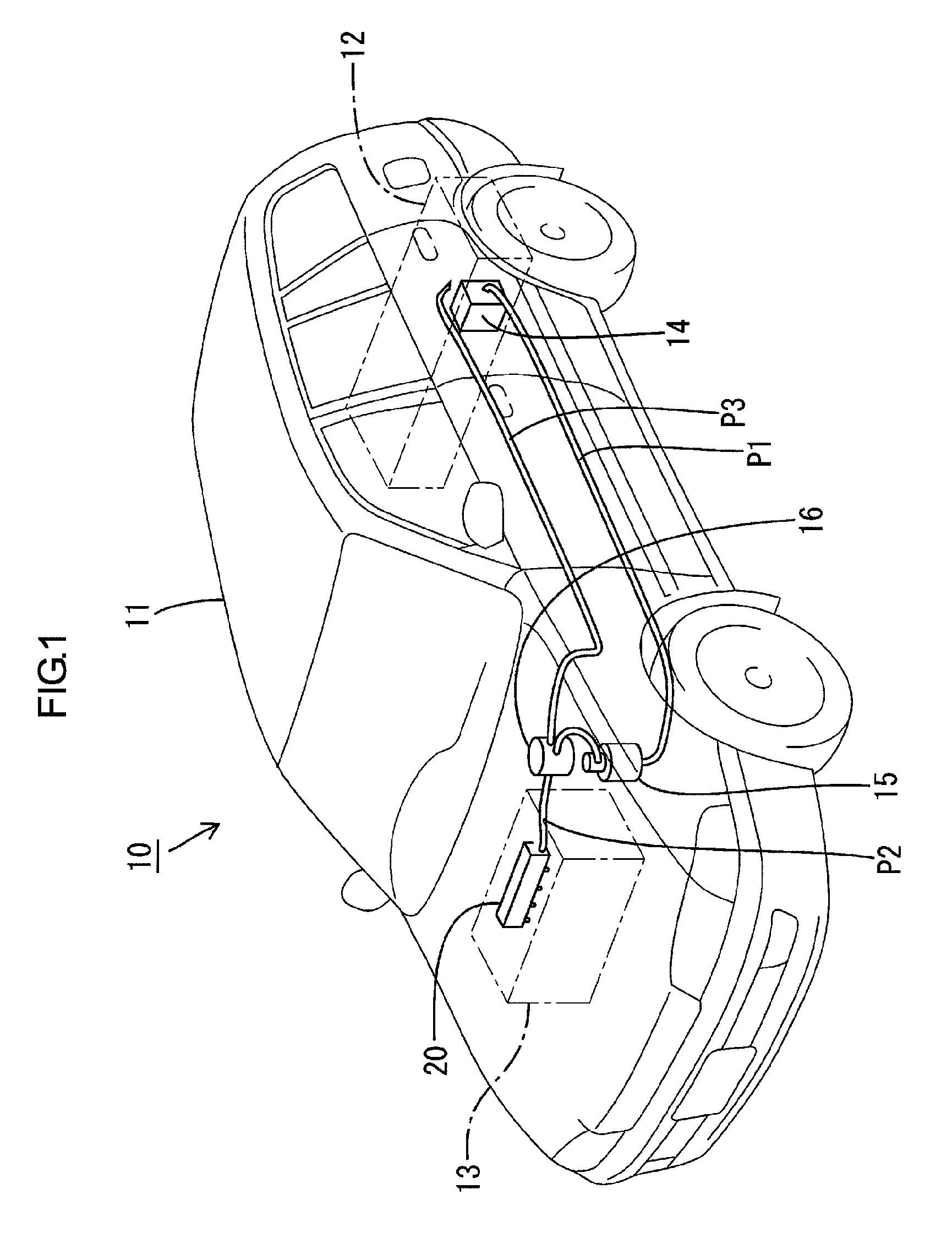
[0021]An embodiment will be described with reference to FIGS. 1 through 7. An overall configuration of fuel system parts according to the present invention will first be described with reference to FIGS. 1 through 4. FIG. 1 is a perspective view illustrating the fuel system parts mounted to a vehicle body 11 of a vehicle 10. The fuel system parts are parts that have respective contact surfaces that contact fuel between a fuel tank 12 and an engine 13. Specifically, the fuel system parts are configured by the fuel tank 12, a fuel supply pump 14, a fuel transfer pipe P1, a fuel transfer pipe P2, a fuel return pipe P3, a filter 15, a pressure regulator 16, etc.
[0022]The fuel tank 12 is disposed in a rear area in the vehicle body 11. The engine 13 is disposed in a front area in the vehicle body 11. The fuel supply pump 14 is disposed in the fuel tank 12 and pressurizes fuel to pump it to the engine 13. The fuel pressurized by the fuel supply pump 14 is transferred through the fuel trans...
PUM
 Abstract
Description
Claims
Application Information