
Corrugated tube connector

a corrugated tube and connector technology, applied in the field of corrugated tube connectors, can solve the problems of b1 in the reliance on the integrity and durability of just a flared metal-to-metal seal, and b75 in the reliance on the sealing qualities of a non-flared metal-to-metal seal. achieve the effect of preventing the seal, maximizing the diameter of the fitting passageway, and easy replacemen

Active Publication Date: 2016-06-21
IVETT JONATHON LACHLAN
View PDF11 Cites 3 Cited by
  • Summary
  • Abstract
  • Description
  • Claims
  • Application Information

AI Technical Summary

Benefits of technology

The present invention provides a connector assembly for tubing that offers enhanced strength and durability compared to previous designs. It achieves this by combining the sealing qualities of a seal with the use of a double flare connection between the tubing and connector. The connector is also less reliant on high quality manufactured parts with minimal surface imperfections. The collet of the connector is designed to securely fit over the tubing and improve the seal between the tubing, collet, and connector. It can be placed on the tubing either way round, making it convenient for installation. The collet includes a shoulder that reduces bunching of the corrugated tube within the fitting, ensuring a even seal.

Problems solved by technology

A disadvantage of EP 0 853 742 B1 lies in the reliance on the integrity and durability of just a flared metal-to-metal seal.
A disadvantage of U.S. Pat. No. 4,674,775 lies in the reliance on the sealing qualities of a non-flared metal-to-metal seal.

Method used


Image

  • Corrugated tube connector
  • Corrugated tube connector
  • Corrugated tube connector

Examples


first embodiment

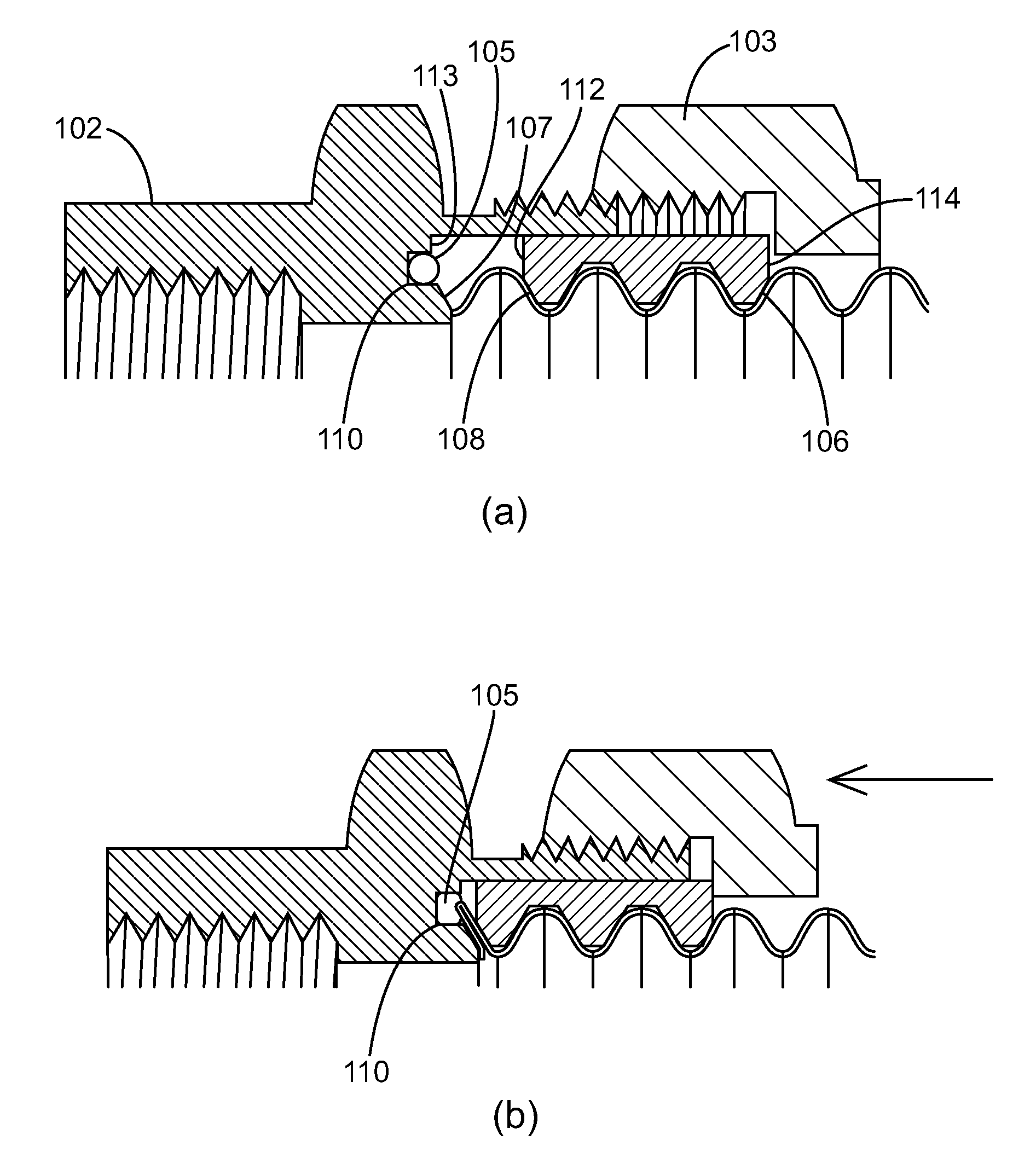
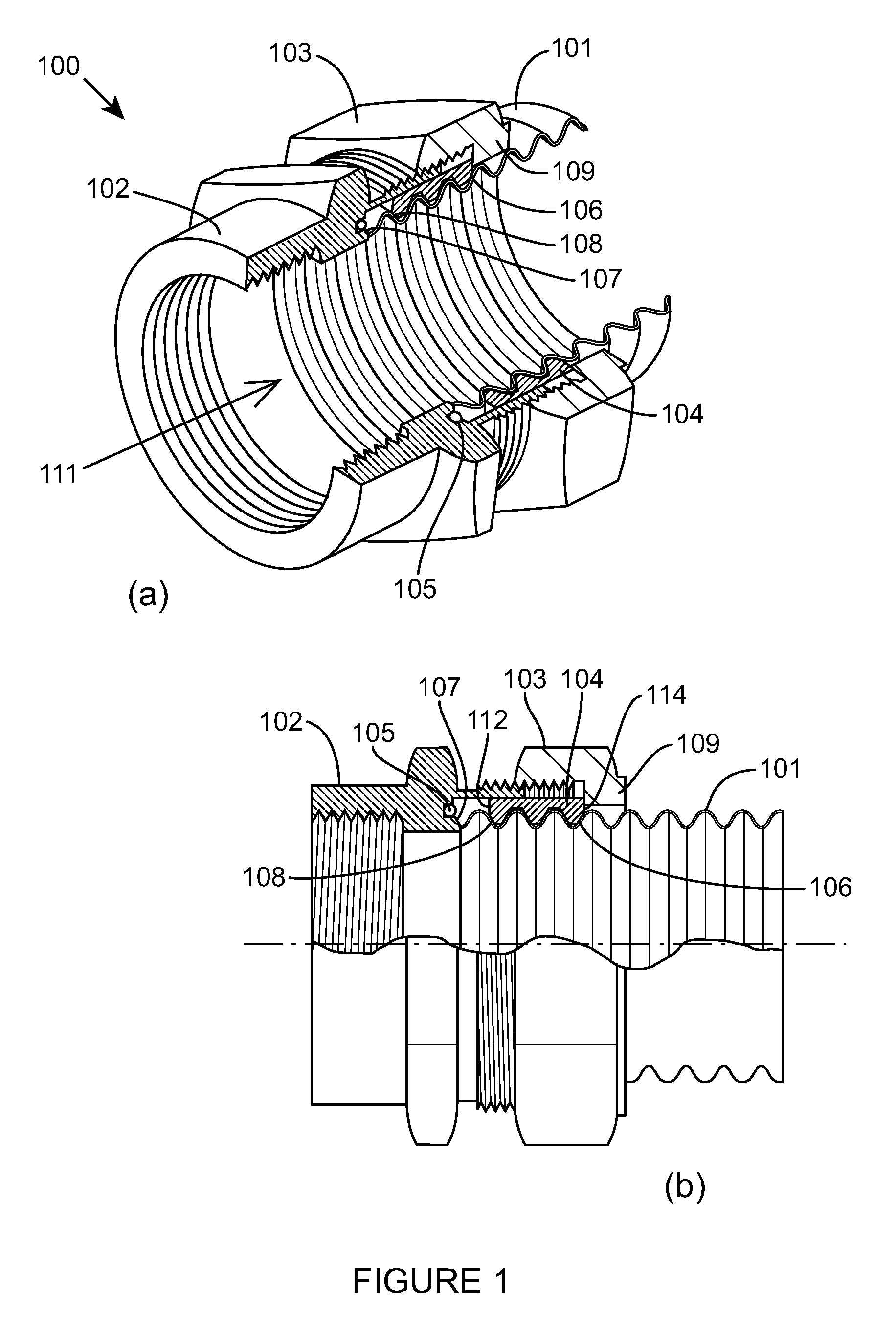
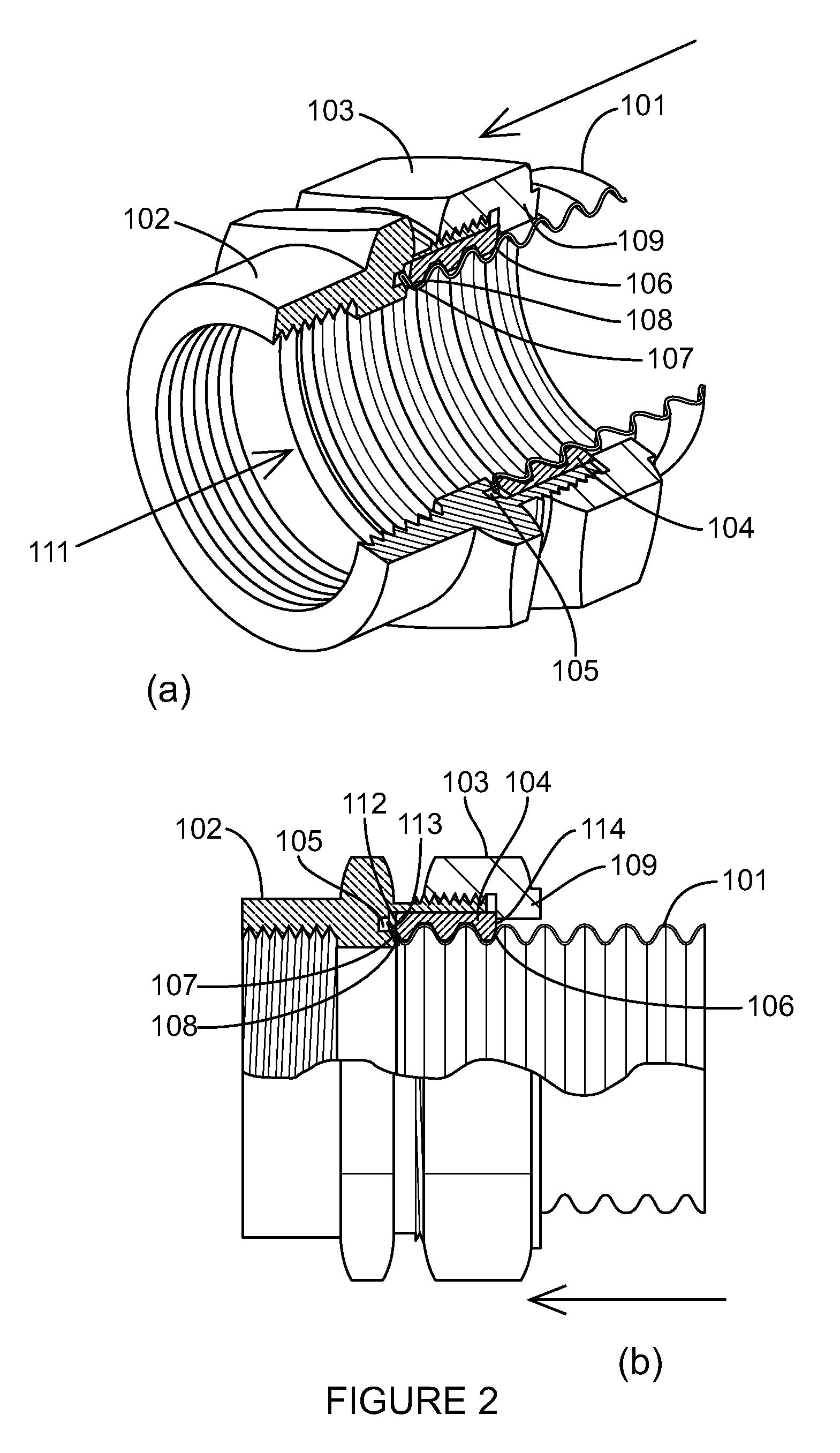
[0061]the invention will now be described with reference to FIGS. 1 to 3. Referring firstly to FIGS. 1(a) and 1(b), a predominantly cylindrical connector assembly 100 is shown which, in use, is connected at one end to a corrugated stainless steel tube 101 and at the other end to an apparatus (not shown). The connection between the tubing and the connector is substantially hermetic and will be described in more detail below.

[0062]References to the tubing 101 are references to the connector assembly 100 when in use.

[0063]The connector assembly 100 comprises a fitting 102, an axial loading nut 103, a collet 104, a seal in the form of an elastomeric 0-ring 105 and a clamping surface 107. As used herein, the term “proximal” refers to a point, location, end or the like which, in use, is closest to the clamping surface 107. The term “distal” refers to a point, location, end or the like which, in use, is furthest from the clamping surface 107. The fitting 102 is cannular, with a through pas...

third embodiment

[0078]FIG. 7 illustrates the invention. In this embodiment the fitting 102 does not comprise an 0-ring 105 in a recess 110 located in the fitting end face 113, rather the tubing 101 is hermetically sealed against a copper gasket 120 provided on the clamping surface 107 and said fitting end face 113.

[0079]The gasket 120 is an annulus comprised of a frusto-conical portion 121 and a rim 122. The frusto-conical portion 121 is sized so as to engage with substantially all the tapered clamping surface 107 and the rim 122 extends radially outward from said frusto-conical portion 121 so as to engage with substantially all the fitting end face 113 of the fitting 102.

[0080]The gasket 120 is sized so as to be closely pressfittingly received by the tapered clamping surface 107 and end face 113. An interior face 123 of the fitting 102 extends from the radially outermost end of the fitting end face 113 and parallel to the longitudinal axis of the fitting 102 toward the tube 101, collet 104 and nut...


PUM


Abstract

A connector for a length of corrugated tubing. The connector includes a fitting including a passage therethrough, a clamping surface, a seal, and a nut operably connected to the fitting. The tubing is in fluid communication with the passage through the fitting. Axial movement of the nut towards the clamping surface-urges the tubing against the seal wherein the tubing is thereby sealingly restrained to the fitting and a clamping surface is formed capable of causing an end portion of the corrugated tube to form a flare by the end portion of the corrugated tube being compressed against the clamping surface and the seal and sealed thereagainst by the action of the nut.

Description

BACKGROUND OF THE INVENTION[0001]The present invention relates to a connector for use with corrugated tubing, and more specifically but not exclusively, to a connector including an 0-ring for sealing corrugated tubing to said connector.[0002]Corrugated tubing is widely used as a conduit in the gas industry and it is a common requirement that such tubing is easily and hermetically attachable to a multitude of devices. As a result, many different forms of hermetically sealable connectors for use specifically with corrugated tubing exist, the desirable characteristics of which include ease of manufacture and assembly, and durability and maintainability of the seal during use.[0003]An example of a connector for corrugated tubing is disclosed in EP 0 853 742 B1 which describes a fitting including a locating sleeve. The fitting is installed by cutting the tubing in a valley in the surface of the tubing and placing a nut over the tubing. Two split ring washers are placed in a valley adjace...

Claims


Application Information

Patent Timeline
Patent Type & Authority Patents(United States)
IPC IPC(8): F16L25/00F16L19/02
CPCF16L19/02F16L25/0036F16L25/0054F16L19/04F16L25/00
Inventor IVETT, JONATHON LACHLAN
Owner IVETT JONATHON LACHLAN
Learn More