High resolution microscope and image divider assembly

a high-resolution, microscope technology, applied in the field of microscopy, can solve the problems of limited image field, distortion of the spot of the molecule, and the method of high-resolution based on localization described above,

Active Publication Date: 2016-06-21
CARL ZEISS MICROSCOPY GMBH
View PDF14 Cites 4 Cited by
  • Summary
  • Abstract
  • Description
  • Claims
  • Application Information

AI Technical Summary

Problems solved by technology

The method of high resolution based on localization described above is, however, limited to surfaces of two dimensions, since the localization of each dye molecule is incomparably more complex in the third spatial dimension (z-direction).
A problem with this method is that the local environment and the orientation of the molecular dipole can also result in a distortion of the spot of the molecule (see above references).
The latter will naturally result in a limitation of the image field.
However, the solutions described in the above references have the following disadvantages and limitations:Oblique incidence on the image sensor causes distortions of the PSF depending on the z-position; the center of gravity is laterally dependent on the z-position;The imaging scale changes as a function of the z-position;Splitting cannot be adjusted, meaning that the optimal working point cannot be adjusted for different microscope objectives;If an adjustment were (theoretically) made (such as by the mirror method described in [8]), it would be impossible to set the z-splitting on both planes to “zero,” due to a longer beam path in air;An adjustment made in this way would shift the moved object plane into the cover glass at an increased z-splitting when measuring objects near the cover glass in high resolution, requiring refocusing of the entire system.The problem to be overcome by the present invention therefore is splitting a microscope image into two partial images on two partial areas of an image sensor while avoiding the disadvantages and limitations mentioned above.

Method used


Image

  • High resolution microscope and image divider assembly
  • High resolution microscope and image divider assembly
  • High resolution microscope and image divider assembly

Examples


Embodiment Construction

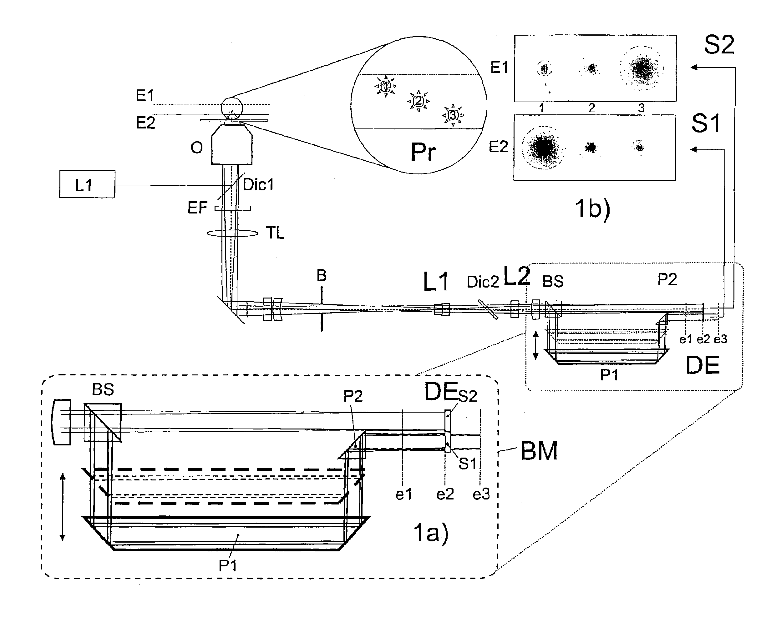
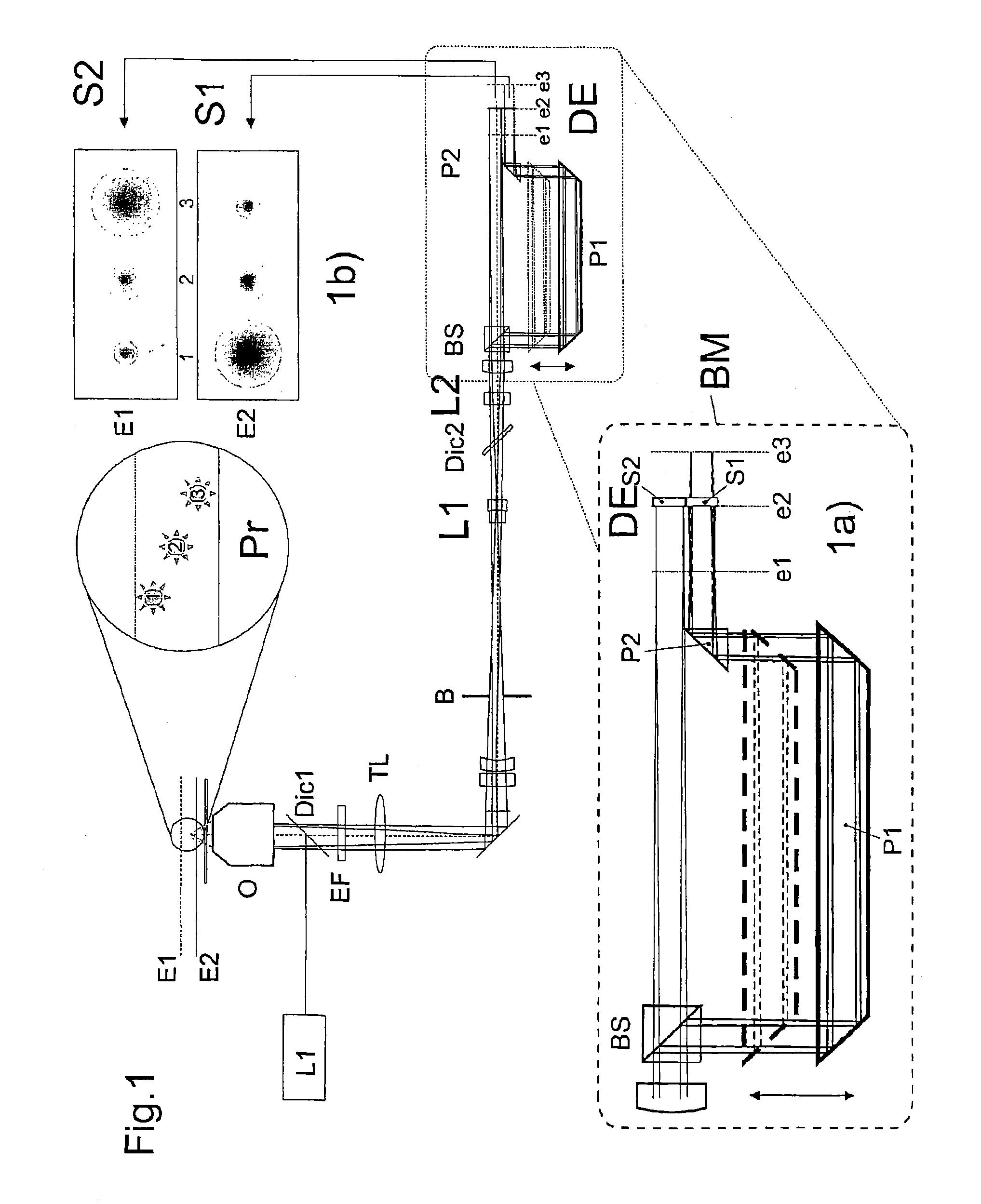
[0066]FIG. 1 shows a wide field beam path with a dilated light source and a spatially resolved planar detector such as a CCD camera.

[0067]The light from light source L1 reaches the sample Pr (reflected) via Dic 1 and the objective O. The reflected and fluorescent sample light passes through the objective in the direction of detection. Selection of the desired portion of the light is performed at splitter Dic 1 through filter EF, i.e. the reflected light is suppressed, and only the fluorescent light passes on in the direction of detection. The sample light reaches the arrangement according to the invention consisting of BS, P1, and P2 and then the detector DE via SP, L1, and L2, E1 and E2 are different object planes in the sample Pr.

[0068]FIG. 1a shows an enlarged view of the variable image splitter module BM according to the invention. An image of the sample Pr is split via the beam-splitter cube BS into two partial images on the detector DE. The prism P1 is moved by a motor perpend...


PUM


Abstract

The invention relates to a microscope having an illumination beam path with wide field illumination of a sample and a first detection beam path having a spatially resolved surface receiver, which is reached by a first part of the detection light coming from the sample via the first detection beam path, or an image divider assembly for a microscope. In order to lengthen the optical path length, at least a second part of the detection light coming from the sample is masked out of the detection beam path and, via deflection means belonging to the detection beam path, is led into a second detection beam path and, preferably via further deflection means, is deflected back in the direction of the detection in such a way that detection light is applied to at least two partial regions beside one another on the surface receiver. At least the second part of the detection light runs in an optical element having an optical density that is increased as compared with the first detection beam path, in order to lengthen the optical path length, and the optical element is designed to be displaceable at an angle, preferably perpendicular, to the optical axis of the first detection beam path in order to adjust the optical path length, and has flat surfaces, at least on the light entry and light exit side thereof; a prism is provided, preferably a glass prism, preferably at least in the second detection beam path after a first beam deflection, for deflection in a direction parallel to the first detection beam path, in order to increase the path length and for reverse deflection.

Description

RELATED APPLICATIONS[0001]The present application is a U.S. National Stage application of International PCT Application No. PCT / EP2010 / 007594 filed on Dec. 14, 2010 which claims priority benefit of German Application No. DE 10 2009 060 490.1 filed on Dec. 22, 2009, the contents of each are incorporated by reference in their entirety.FIELD OF THE INVENTION[0002]The present invention relates generally to the field of microscopy and more particularly to high-resolution microscopy.BACKGROUND OF THE INVENTION[0003]The background of the invention can be appreciated from the following literature:[0004][1] Betzig et al, Science 313, pp. 1642-1645 (2006);[0005][2] Hess et al., PNAS 104, pp. 17370-17375 (2007);[0006][3] Hess et al., Biophys J. 91, pp. 4258-427 (2006);[0007][4] Shroff et al., PNAS 104, pp. 20308-2031 (2007);[0008][5] Rust et al., Nature Methods 3, pp. 793-796 (2006);[0009][6] Egner et al., Biophys J. 93, pp. 3285-3290 (2007);[0010][7] Toprak et al., Nano Lett. 7, pp. 2043-2045...

Claims


Application Information

Patent Timeline
Patent Type & Authority Patents(United States)
IPC IPC(8): G02B21/18G02B21/16G02B17/02G02B21/36G02B27/10G02B27/58G02B27/14G02B7/38G02B21/00G02B21/24
CPCG02B17/023G02B21/16G02B21/18G02B21/367G02B27/106G02B27/1066G02B27/141G02B27/144G02B27/145G02B21/361G02B27/58G02B7/38G02B21/0088G02B21/245G01N21/6458G02B21/0032G02B21/0072G02B21/0076
Inventor KALKBRENNER, THOMASGOELLES, MICHAEL
Owner CARL ZEISS MICROSCOPY GMBH
Why Eureka
Try Eureka