Supercharge Your Innovation With Domain-Expert AI Agents!

Power control unit and method for controlling electrical power provided to a load, in particular an LED unit, and voltage control unit for controlling an output voltage of a converter unit

a technology of power control unit and output voltage, which is applied in the direction of lighting apparatus, electroluminescent light sources, light sources, etc., can solve the problems of not always providing a significant edge of voltage step, increasing the power loss of lamps, and not being able to precisely detect the phase angle of phase cut voltage, etc., to achieve high efficiency, reduce losses, and high power factor

Inactive Publication Date: 2016-06-28
SIGNIFY HLDG BV +1
View PDF9 Cites 2 Cited by
  • Summary
  • Abstract
  • Description
  • Claims
  • Application Information

AI Technical Summary

Benefits of technology

The solution achieves high efficiency and reduced power loss with low technical effort by providing a deterministic relationship between the switching device activation and signal application, minimizing unnecessary bleeding and allowing precise detection of phase cut-offs.

Problems solved by technology

Trailing edge phase cut dimmers, which are preferably used, do not always provide a voltage step with a significant edge, which is easy to detect due to the filter capacitors across the lamp and across the dimmer.
This is a technically complicated solution to detect the edge of the phase cut signal and increases the power loss in the lamps.
A detection of the phase angle of the phase cut voltage is not precisely possible with this bleeder circuit.

Method used


Image

  • Power control unit and method for controlling electrical power provided to a load, in particular an LED unit, and voltage control unit for controlling an output voltage of a converter unit
  • Power control unit and method for controlling electrical power provided to a load, in particular an LED unit, and voltage control unit for controlling an output voltage of a converter unit
  • Power control unit and method for controlling electrical power provided to a load, in particular an LED unit, and voltage control unit for controlling an output voltage of a converter unit

Examples


first embodiment

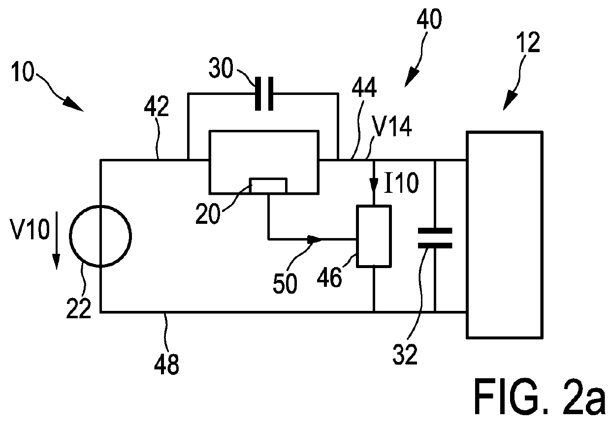
[0051]a power control unit 40 according to the present invention is schematically shown in FIG. 2a. The power control unit 40 comprises the dimmer 10 including the control unit 20 for converting the input voltage V10 provided to an input terminal 42 to an output voltage V14 at an output terminal 44. The dimmer 10 is preferably identical with the dimmer 10 of FIG. 1a. The LED unit 12 is preferably identical with the LED unit 12 of FIG. 1a and represents generally a load of the driver device 40. The capacitor 32 (e.g. 100 nF) is connected in parallel to the LED unit 12. In parallel to the LED unit a current control unit 46 is connected to the output terminal 44 and to a neutral line 48 or a neutral potential 48 of the input voltage supply 22. The current control unit 46 is connected to the control unit 20. The control unit 20 provides a control signal 50 to the current control unit 46. The current control unit 46 is provided for applying a signal to the output terminal 44.

[0052]The cu...

second embodiment

[0073]a voltage control unit 110 is shown in FIG. 5b. The voltage control unit 110 comprises the current control unit 62 of FIG. 3b, a first connection terminal 112 for connecting the current control unit 62 to the output terminal 42 and a second connection terminal 114 for connecting the current control unit 62 to the input terminal 44. Further, the voltage control unit 110 comprises measurement means 116 connected to the output terminal 44 for measuring the output voltage V12 and for detecting a change in the output voltage corresponding to the switching off of the switch 14 indicating the cut-off of the supply voltage V12. The measurement means 116 provide two control signals 118, 120 to the controllable switches 74, 76 in line with the control signals 82, 84 shown in FIG. 3b. Hence, the voltage control unit 110 can be connected in parallel to an existing dimmer 10 as an add-on module and provides a significant and easy to detect step or edge when the phase cut dimmer 10 cuts the...


PUM


Abstract

The present invention relates to a power control unit (40; 60) for controlling electrical power provided to a load (12), in particular an LED unit (12) comprising one or more LEDs, said driver device comprising a converter unit (10) having an input terminal (42) for receiving an input voltage (V10) from an external power supply (22) and having an output terminal (44) for providing an output voltage (V14) to power the load (12), wherein the converter unit (10) comprises a switching device (14) for transforming the input voltage (V10) to the output voltage (V14), a control unit (20) for controlling the switching device (14), signal means (46; 62) connected to the output terminal (44) for applying a voltage or current signal to the output terminal (44), wherein the control unit (20) is connected to the signal means (46; 62) and adapted to control the signal means (46; 62).

Description

FIELD OF THE INVENTION[0001]The present invention relates to a power control unit and a corresponding method for controlling electrical power provided to a load, in particular an LED unit comprising one or more LEDs. Further, the present invention relates to a voltage control unit for controlling an output voltage of a converter unit. Further, the present invention relates to a light apparatus.BACKGROUND OF THE INVENTION[0002]In the field of LED drivers for offline applications such as retrofit lamps and new lamps or modules solutions are demanded to cope with high efficiency, high power density and high power factor among other relevant features. While practically all existing solutions comprise one or the other requirement, it is essential that the proposed driver circuit properly condition the form of the mains energy into the form required by the LEDs while keeping compliance with present and future power mains regulations. Of critical importance is to control the amount of powe...

Claims


Application Information

Patent Timeline
Patent Type & Authority Patents(United States)
IPC IPC(8): H05B37/02H05B33/08H05B44/00
CPCH05B33/0815H05B33/0842H05B45/3575H05B45/3725H05B45/31H05B45/37
Inventor RADERMACHER, HARALD JOSEF GUNTHER
Owner SIGNIFY HLDG BV
Features
  • R&D
  • Intellectual Property
  • Life Sciences
  • Materials
  • Tech Scout
  • Unparalleled Data Quality
  • Higher Quality Content
  • 60% Fewer Hallucinations
Learn More