Imaging lens and imaging apparatus equipped with the imaging lens

a technology of imaging lens and imaging apparatus, which is applied in the direction of optics, instruments, optics, etc., can solve the problem of difficult application of this imaging lens to a compact imaging element capabl

Active Publication Date: 2016-07-05
JIANGXI OFILM OPTICAL CO LTD
View PDF5 Cites 12 Cited by
  • Summary
  • Abstract
  • Description
  • Claims
  • Application Information

AI Technical Summary

Benefits of technology

[0062]Conditional Formula (1) defines a preferable range of numerical values for the ratio of the focal length f of the entire system with respect to the combined focal length f12 of the first lens L1 and the second lens L2. The combined refractive power of the first lens L1 and the second lens L2 will not become excessively weak with respect to the refractive power of the entire system, by securing a combined refractive power of the first lens L1 and the second lens L2 such that the value of f / f12 does not become less than or equal to the lower limit defined in Conditional Formula (1). As a result, the total length of the lens system can be shortened favorably. It is more preferable for the lower limit of Conditional Formula (1-1) to be satisfied, and even more preferable for the lower limit of Conditional Formula (1-2) to be satisfied, in order to cause this advantageous effect to become more prominent. In addition, by maintaining the combined refractive power of the first lens L1 and the second lens L2 such that the value of f / f12 is not greater than or equal to the upper limit defined in Conditional Formula (1-1), the combined refractive power of the first lens L1 and the second lens L2 will not be excessively strong with respect to the refractive power of the entire system. As a result, spherical aberration and longitudinal chromatic aberration can be favorably corrected. It is more preferable for the upper limit of Conditional Formula (1-2) to be satisfied, in order to cause these advantageous effects to become more prominent.
[0063]It is preferable for the focal length f2 of the second lens L2 and the focal length f of the entire system to satisfy Conditional Formula (2) below.f / f2<−0.1  (2)Conditional Formula (2) defines the preferred range of numerical values for the ratio of the focal length f of the entire system with respect to the focal length f2 of the second lens L2. By securing the refractive power of the second lens L2 such that the value of f / f2 is not greater than or equal to the upper limit defined in Conditional Formula (2), the negative refractive power of the second lens L2 will not become excessively weak with respect to the refractive power of the entire system. As a result, longitudinal chromatic aberration can be favorably corrected. It is more preferable for the upper limit of Conditional Formula (2-1) to be satisfied, and even more preferable for the upper limit of Conditional Formula (2-2) to be satisfied, in order to cause this advantageous effect to become more prominent. In addition, it is preferable for the refractive power of the second lens L2 to be maintained such that the value of f / f2 is not less than or equal to the lower limit defined in Conditional Formula (2). In this case, the negative refractive power of the second lens L2 will not become excessively strong with respect to the refractive power of the entire system. As a result, the total length of the lens system can be shortened favorably. It is more preferable for the lower limit of Conditional Formula (2-2) to be satisfied, in order to cause this advantageous effect to become more prominent.−1<f / f2<−0.2  (2-1)−0.8<f / f2<−0.2  (2-2)
[0064]In addition, it is preferable for the focal length f1 of the first lens L1 and the focal length f of the entire system to satisfy Conditional Formula (3) below.0<f / f1<2.5  (3)Conditional Formula (3) defines the preferred range of numerical values for the ratio of the focal length f of the entire system with respect to the focal length f1 of the first lens L2. By securing the refractive power of the second lens L1 such that the value of f / f1 is not less than or equal to the lower limit defined in Conditional Formula (3), the refractive power of the first lens L1 will not become excessively weak with respect to the refractive power of the entire system. As a result, the total length of the lens system can be favorably shortened. In addition, it is preferable for the refractive power of the first lens L1 to be maintained such that the value of f / f1 is not greater than or equal to the upper limit defined in Conditional Formula (3). In this case, the refractive power of the first lens L1 will not become excessively strong with respect to the refractive power of the entire system. As a result, spherical aberration can be favorably corrected. It is more preferable for Conditional Formula (3-1) to be satisfied, and even more preferable for Conditional Formula (3-2) to be satisfied, in order to cause these advantageous effects to become more prominent.0.5<f / f1<2  (3-1)0.55<f / f2<1.5  (3-2)
[0065]In addition, it is preferable for the focal length f3 of the third lens L3 and the focal length f of the entire system to satisfy Conditional Formula (4) below.0<f / f3  (4)Conditional Formula (4) defines a preferable range of numerical values for the ratio of the focal length f of the entire system with respect to the focal length f3 of the third lens L3. The refractive power of the third lens L3 will not become excessively weak with respect to the refractive power of the entire system, by securing a refractive power of the third lens L3 such that the value of f / f3 does not become less than or equal to the lower limit defined in Conditional Formula (4). As a result, the total length of the lens system can be shortened favorably. It is more preferable for the lower limit of Conditional Formula (4-1) to be satisfied, and even more preferable for the lower limit of Conditional Formula (4-2) to be satisfied, in order to cause this advantageous effect to become more prominent. In addition, by maintaining the refractive power of the third lens L3 such that the value of f / f3 is not greater than or equal to the upper limit defined in Conditional Formula (4-1), the refractive power of the third lens L3 will not be excessively strong with respect to the refractive power of the entire system. As a result, spherical aberration can be favorably corrected. It is more preferable for the upper limit of Conditional Formula (4-2) to be satisfied, in order to cause this advantageous effect to become more prominent.0.32<f / f3<1  (4-1)0.35<f / f3<0.6  (4-2)
[0066]In addition, it is preferable for the focal length f4 of the fourth lens L4 and the focal length f of the entire system to satisfy Conditional Formula (5) below.f / f4<0  (5)Conditional Formula (5) defines a preferable range of numerical values for the ratio of the focal length f of the entire system with respect to the focal length f4 of the fourth lens L4. The refractive power of the fourth lens L4 will not become excessively weak with respect to the refractive power of the entire system, by securing a refractive power of the fourth lens L4 such that the value of f / f4 does not become greater than or equal to the upper limit defined in Conditional Formula (5). As a result, field curvature can be favorably corrected, particularly at intermediate angles of view. It is more preferable for the upper limit of Conditional Formula (5-1) to be satisfied, and even more preferable for the upper limit of Conditional Formula (5-2) to be satisfied, in order to cause this advantageous effect to become more prominent. In addition, by maintaining the refractive power of the fourth lens L4 such that the value of f / f4 is not less than or equal to the lower limit defined in Conditional Formula (5-1), the negative refractive power of the fourth lens L4 will not be excessively strong with respect to the refractive power of the entire system. As a result, chromatic aberration in the vicinity of the optical axis can be suppressed. It is more preferable for the lower limit of Conditional Formula (5-2) to be satisfied, in order to cause this advantageous effect to become more prominent.−0.65<f / f4<0  (5-1)−0.6<f / f4<−0.1  (5-2)
[0067]In addition, it is preferable for the thickness Da of the first lens L1 along the optical axis and the focal length f of the entire system to satisfy Conditional Formula (6) below.0.08<Da / f  (6)Conditional Formula (6) defines a preferable range of numerical values for the ratio of the thickness Da of the first lens L1 along the optical axis with respect to the focal length f of the entire system. By securing a thickness Da of the first lens L1 along the optical axis with respect to the focal length f of the entire system such that the value of Da / f is not less than or equal to the lower limit defined in Conditional Formula (6), astigmatism can be favorably corrected, and the thickness of the peripheral portions of the first lens L1 becoming excessively thin can be suppressed, which is advantageous from the viewpoint of production. It is more preferable for the lower limit of Conditional Formula (6-1) to be satisfied, and even more preferable for the lower limit of Conditional Formula (6-2) to be satisfied, in order to cause these advantageous effects to become more prominent. In addition, by maintaining the thickness Da of the first lens L1 along the optical axis such that the value of Da / f does not become greater than or equal to the upper limit defined in Conditional Formula (6-1), the distance between the surface of the first lens L1, which has a positive refractive power, toward the object side and an entrance pupil can be maintained so as to not be excessively great. As a result, an increase in the effective diameter of the first lens L1 can be suppressed. It is more preferable for the upper limit defined in Conditional Formula (6-2) to be satisfied, in order to cause this advantageous effect to become more prominent. Note that in each of the Examples, the thickness Da of the first lens L1 along the optical axis corresponds to D1 shown in Tables 1, 3, 5, 7, 8, and 11 to be described later.0.1<Da / f<0.3  (6-1)0.12<Da / f<0.2  (6-2)

Problems solved by technology

The imaging lens disclosed in Japanese Unexamined Patent Publication No. 7 (1995)-281089 has a large F number, and it is difficult for this imaging lens to be applied to a compact imaging element capable of realizing a required degree of high resolution in order to meet this demand.

Method used


Image

  • Imaging lens and imaging apparatus equipped with the imaging lens
  • Imaging lens and imaging apparatus equipped with the imaging lens
  • Imaging lens and imaging apparatus equipped with the imaging lens

Examples


Embodiment Construction

[0040]Hereinafter, embodiments of the present invention will be described in detail with reference to the attached drawings.

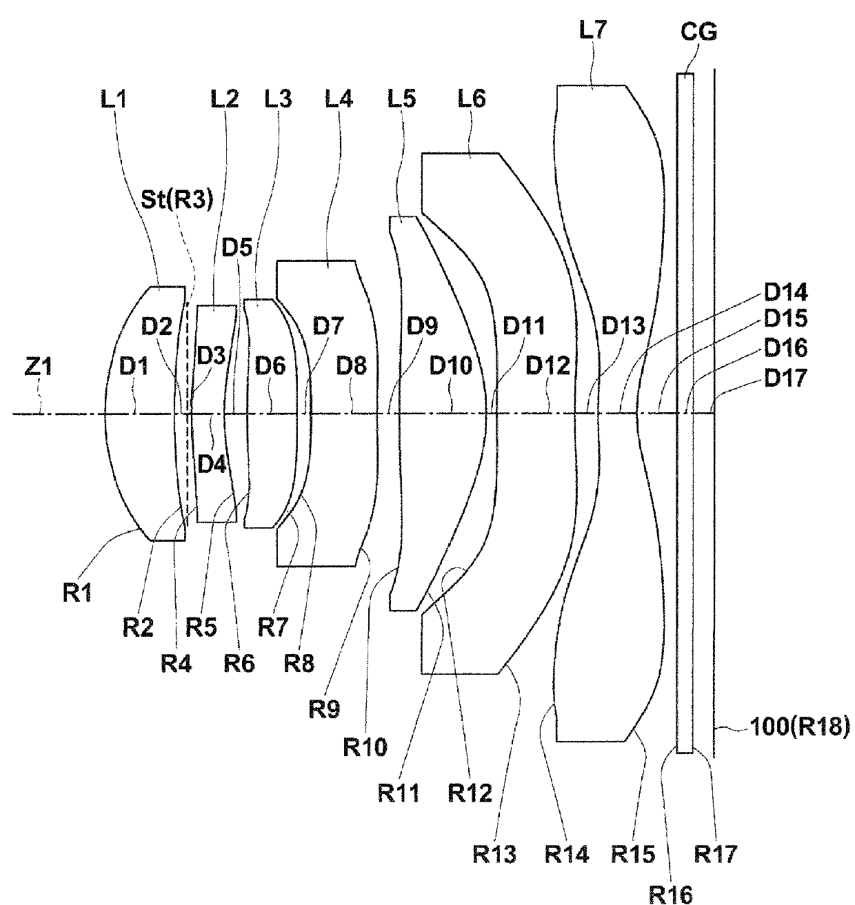
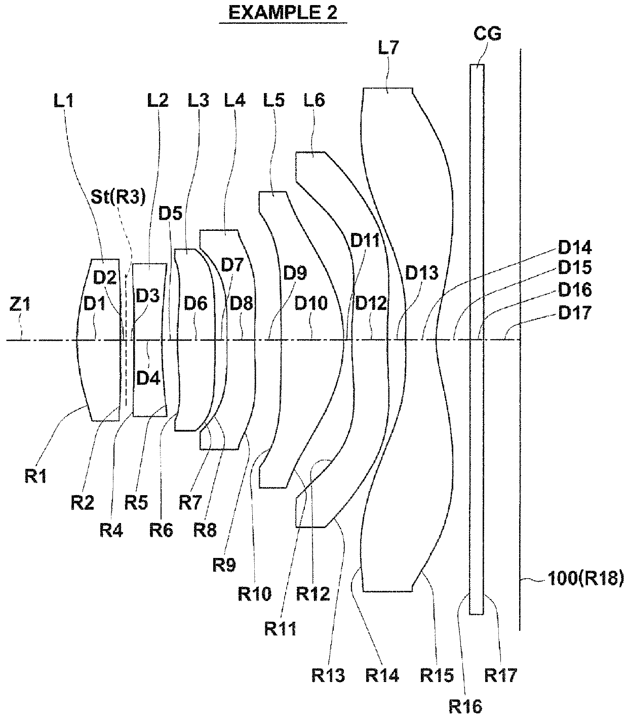
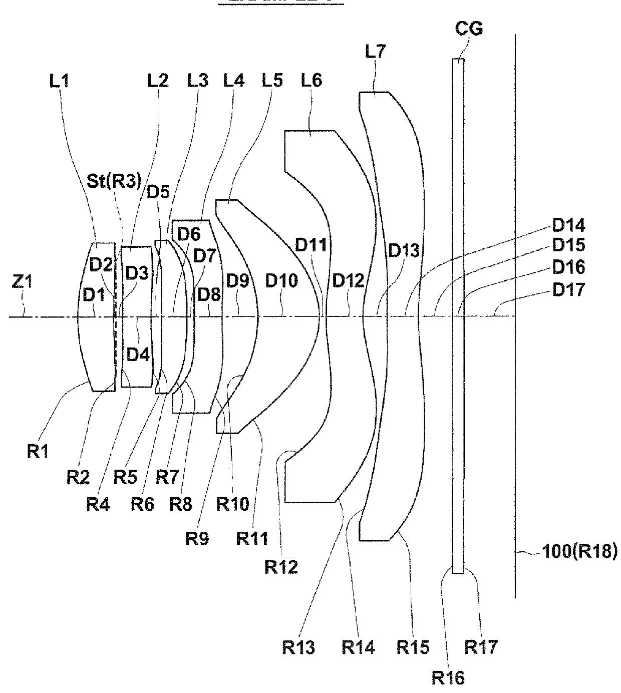
[0041]FIG. 1 illustrates a first example of the configuration of an imaging lens according to an embodiment of the present invention. This example corresponds to the lens configuration of Numerical Example 1 (Table 1 and Table 2), to be described later. Similarly, FIG. 2 through FIG. 5 and FIG. 14 are sectional diagrams that illustrate second through sixth examples of lens configurations that correspond to Numerical Examples 2 through 6 (Table 3 through Table 12). In FIG. 1 through FIG. 5 and FIG. 14, the symbol Ri represents the radii of curvature of ith surfaces, i being lens surface numbers that sequentially increase from the object side to the image side (imaging side), with the surface of a lens element most toward the object side designated as first. The symbol Di represents the distances between an ith surface and an i+1st surface along an optical axis Z...


PUM


Abstract

An imaging lens substantially includes seven lenses, constituted by: a first lens having a positive refractive power and a convex surface toward an image side; a second lens having a negative refractive power; a third lens having a positive refractive power; a fourth lens; a fifth lens having a positive refractive power; a sixth lens; and a seventh lens having a negative refractive power, a concave surface toward an image side, and at least one inflection point in the surface toward the image side; provided in this order from an object side. All of the first lens through the seventh lens are single lenses.

Description

CROSS REFERENCE TO RELATED APPLICATIONS[0001]The present application claims priority under 35 USC §119 to Japanese Patent Application No. 2013-138595 filed on Jul. 2, 2013 and Japanese Patent Application No. 2014-011158 filed on Jan. 24, 2014. Each of the above applications is hereby expressly incorporated by reference, in its entirety, into the present application.TECHNICAL FIELD[0002]The present invention is related to a fixed focus imaging lens for forming optical images of subjects onto an imaging element such as a CCD (Charge Coupled Device) and a CMOS (Complementary Metal Oxide Semiconductor). The present invention is also related to an imaging apparatus provided with the imaging lens that performs photography such as a digital still camera, a cellular telephone with a built in camera, a PDA (Personal Digital Assistant), a smart phone, and a portable gaming device.BACKGROUND ART[0003]Accompanying the recent spread of personal computers in households, digital still cameras capa...

Claims


Application Information

Patent Timeline
Patent Type & Authority Patents(United States)
IPC IPC(8): G02B9/64G02B13/00
CPCG02B13/0045G02B9/64
Inventor SHINOHARA, YOSHIKAZUISHII, YOSHIAKI
Owner JIANGXI OFILM OPTICAL CO LTD
Why Eureka
Try Eureka